SKA PST RECV Interfaces
Overview
RECV implements the external interface between PST and the Correlator Beamformer (CBF) as described in the CBF to PSR Interface Control Document.
Interface Details
The UDP packet format described in the ICD includes 3 main components:
packet meta-data (96 bytes)
relative weights (variable)
channelized voltage data (variable)
The sizes of the relative weights and channelized voltage data depend on the Beam Former (Low or Mid), the Band (Low, 1, 2, 3, 4, 5) and the Array Assembly. The sizes for each packet are shown in the table below.
Band |
AA |
Nchan |
Nsamp |
Nweight |
Nbit |
Packet Size |
|---|---|---|---|---|---|---|
Low |
All |
24 |
32 |
1 |
16b+16b |
6288 |
Mid 1,2 |
0.5,1 |
185 |
4 |
4 |
16b+16b |
6432 |
Mid 1-3 |
2+ |
1 * |
2048 * |
64 * |
8b+8b * |
8416 |
Mid 4-5 |
2+ |
1 * |
1024 * |
32 * |
16b+16b |
8352 |
* To be Confirmed with Mid.CBF
Packet Details
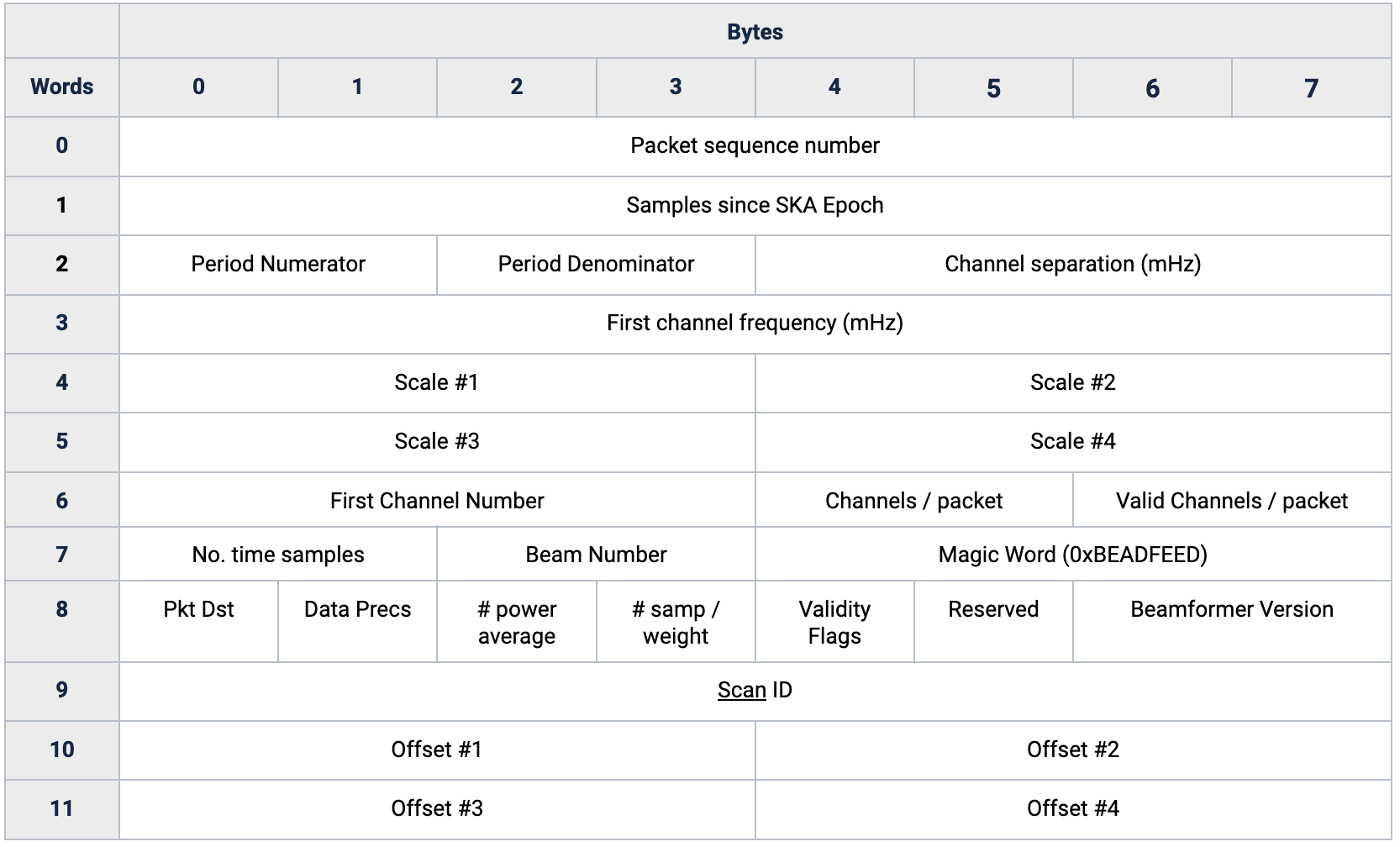
The meta-data in the UDP packets is interpreted by RECV using a C struct that is mapped onto the packed bytes received in the UDP payload. The layout of the packet meta-data is shown below.
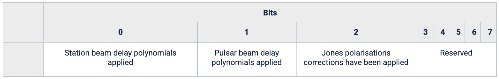
The Validity Flags field is comprised of single bit flags indicating validity of the data in the packet arising from upstream signal processing functions performed by the CBF. The validity bits are shown below.
A description of each of the fields is summarized below.
Parameter |
Comments |
|---|---|
packet sequence number |
counts from 0 at the start of the scan |
samples since ska epoch |
samples since SKA epoch |
sample period numerator |
sample period numerator in microseconds |
sample period denominator |
sample period denominator in microseconds |
channel separation |
frequency spacing between channels in the packet in units of millihertz |
first channel freq |
channel centre frequency of the First Channel Number in the packet in units of millihertz |
scale 1 |
scale factor #1 - value by which CBF voltage data is scaled before conversion to the values in the packet |
scale 2 |
scale factor #2 - Stokes Q [Mid.PSS only] |
scale 3 |
scale factor #3 - Stokes U [Mid.PSS only] |
scale 4 |
scale factor #4 - Stokes V [Mid.PSS only] |
first channel number |
first frequency channel index within the packet |
channels per packet |
number of contiguous frequency channels contained in the packet |
valid channels per packet |
number of valid frequency channels in the packet, always <= channels per packet |
time samples per packet |
number time samples for each frequency channel contained within the packet |
beam number |
beam (of 16 possible beams for PST and 501 for Low.PSS and 1500 for Mid.PSS) to which the data in the packet belongs |
magic word |
enables a basic check of the packet contents during decoding [BEADFEED] |
packet destination |
0=Low.PSS, 1=Mid.PSS, 2=Low.PST, 3=Mid.PST |
data precision |
number of bits per integer value stored in the Channel/Sample data section of the packet |
num power samples averaged |
number voltage time samples, whose power is averaged, for each time sample in the packet. Valid only for Mid.PSS |
num time samples per relative weight |
number of times samples, for each frequency channel, over which a relative weight is calculated |
station beam polynomials applied |
flag indicating if the station beam delay polynomials have been applied |
pst beam polynomials applied |
flag indicating if the PST beam delay polynomials have been applied |
jones polarisation corrections applied |
flag indicating if the Jones polarisation corrections have been applied |
reserved 1 |
reserved byte |
cbf version major |
major release number for the beam-former version |
cbf version minor |
minor release number for the beam-former version |
scan id |
scan ID specified by the LMC |
offset 1 |
Offset #1 - to be added to the corresponding Stokes parameters before applying scale [1..4] |
offset 2 |
Offset #2 - Stokes Q [Mid.PSS only] |
offset 3 |
Offset #3 - Stokes Q [Mid.PSS only] |
offset 4 |
Offset #4 - Stokes Q [Mid.PSS only] |
The relative weights are each stored as a 16-bit unsigned integer where the decimal point is interpreted to be after the most significant bit (value range: 2-2^-16 to zero) and 1 is encoded as 8000hex.
The channelised voltage data are stored as 16-bit, signed integers in Twos Complement binary with Little Endian encoding.
Behaviours
RECV’s primary function is to receive the UDP packets, inspect them and then write the data, weights and scales to the Shared Memory Ring Buffer (SMRB). To achieve this RECV will
Inspect the meta-data of each packet to determine the location in SMRB to write the packet data and weights
Write the scale_1 meta data and relative weights to the SMRB weights ring buffer
Write the channelised voltage data to the SMRB data ring buffer
Validity Flags
RECV supports the inspection and application of the validity flags. RECV supports different validity flag processing policies that affect the treatment of the relative weights block in a packet. The policy, in combination with the validity flags, will control whether RECV will overwrite the relative weights to 0.
IgnoreAll: ignore all validity flags, no changes to relative weights
StationBeamDelayPolynomials: zero the relative weights if the Station Beam Delay Polynomials have not been applied
PSTBeamDelayPolynomials: zero the relative weights if the PST Beam Delay Polynomials have not been applied
JonesMatrices: zero the relative weights if the Jones Matrices have not been applied
AnyDelayPolynomials: zero the relative weights if the Station or PST Beam Delay Polynomials have not been applied
All: zero the relative weights if any of the validity flags are not set.
The default policy for RECV is IgnoreAll, this can be changed programmatically via ska::pst::recv::UDPFormat::set_validity_flags_policy, but is not currently configurable via the control interface with CSP-LMC, this is future work.