SKA PST RECV Architecture
Overview
The purpose of RECV is to acquire the timeseries of tied-array voltages from the Correlator Beam Former (CBF) and write them to the Shared Memory Ring Buffer (SMRB). RECV adds meta-data received from PST LMC during scan configuration to the meta-data that describe the timeseries, thereby providing a complete description of the data stream.
RECV implements the external interface between CBF and PST, further described in the Interfaces section. This interface handles the capture UDP packets transmitted by CBF, re-blocking the data payloads into larger segments and then writing these to the SMRB. These operations are governed by internal interfaces with the MGMT and SMRB.
Each PST Beam will spread the workload of RECV into a number (e.g. 4) of parallel data streams that can be split across the computational resources. The split will occur in the frequency domain, thereby creating multiple sub-bands (i.e. blocks of contiguous channels). The number of sub-bands and size of each sub-band may differ for each processing configuration.
Decomposition
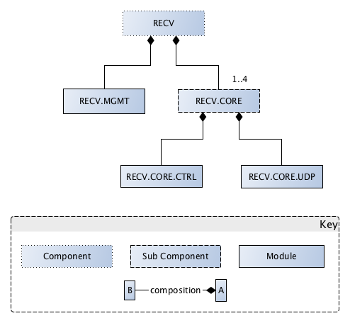
RECV consists of a monitoring and control module (RECV.MGMT) which interacts with the MGMT component and controls the other sub-components of the RECV. RECV.MGMT controls instances of DataBlockManager, one for each sub-band. Each DataBlockManager, contains DataBlock instances for the Data and Weights streams. The DataBlock contains ring buffers for the Header (meta-data) and Data (time-series). Each of these ring buffers have a configurable number of elements and element size. The structure and relationship of of these classes are shown in the figure below.
Data and Control Flow
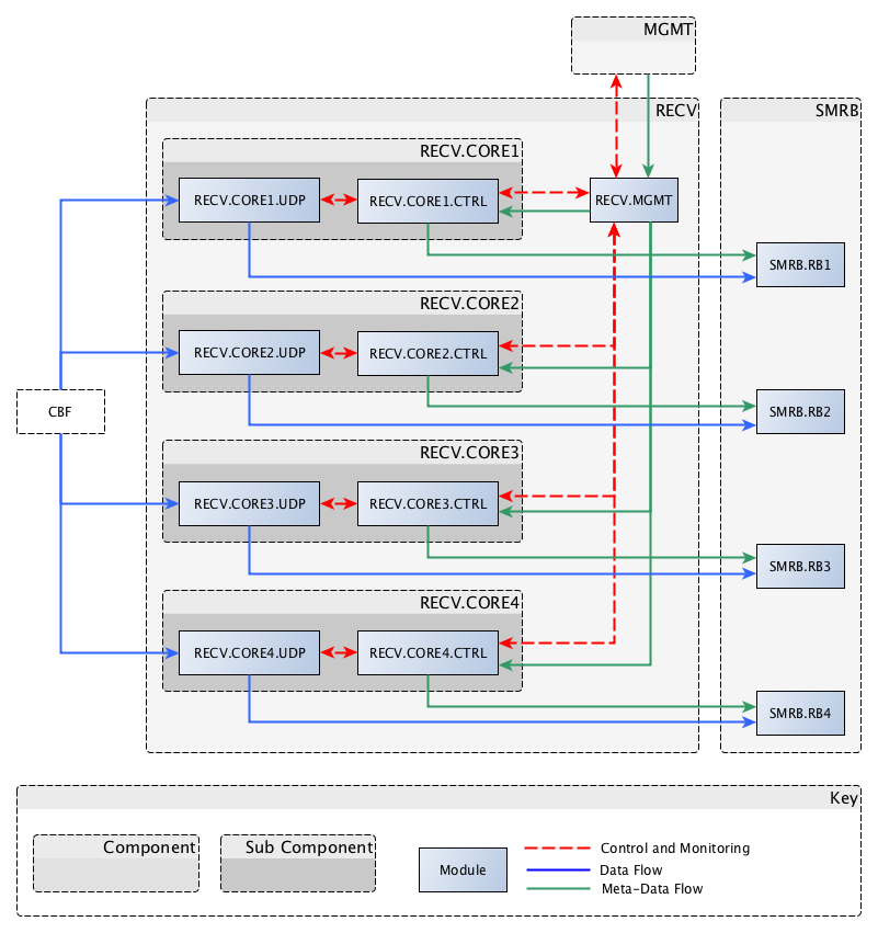
The data and control connections between these sub-components and modules are shown in the Connector and Component diagram below. The RECV component is largely a passive component as the RECV component writes to memory addresses managed by the RECV and the STAT and DSP components read from the same memory addresses.
State Model
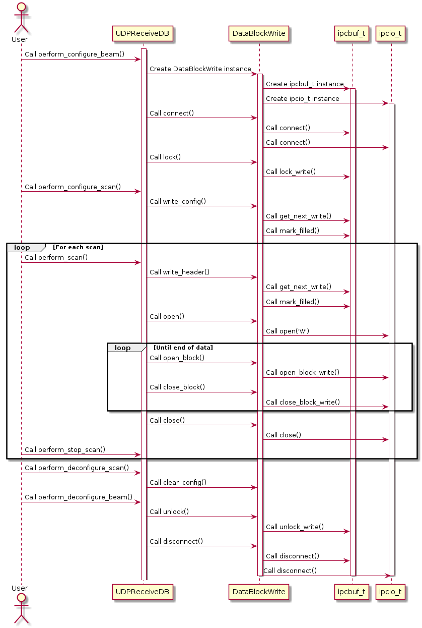
Sequence diagram showing interaction with the ring buffer