MCS to HPS
The interface from the MCS to the HPS is largely in the form of communication between Tango devices running on either side.
The interface also currently consists of low-level SSH calls from the MCS to the Talon-DX boards, which are used to copy FPGA bitstreams and Tango device server binaries to the boards and start the HPS Master process. This functionality may be moved in the future, but for now it is implemented in the TalonDxComponentManager Class, which is instantiated by the CbfController.
MCS and HPS Master DS
The interface between the MCS and the HPS Master device server is primarily made up
of the configure command sent from the MCS to the HPS master, which programs the
FPGA and spawns the remaining HPS device servers. Before this command can be run, it is
expected that the MCS has already copied the necessary bitstreams and binaries to the board
and the HPS master has obviously been started. This is all handled automatically as part of
the MCS On Command.
The configure command has one argument, which is a JSON-formatted string. An example
of its contents can be seen below.
{
    "description": "Configures Talon DX to run VCC firmware and devices.",
    "target": "talon1",
    "ip_address": "169.254.100.1",
    "ds_hps_master_fqdn": "talondx-001/hpsmaster/hps-1",
    "fpga_path": "/lib/firmware",
    "fpga_dtb_name": "vcc3_2ch4.dtb",
    "fpga_rbf_name": "vcc3_2ch4.core.rbf",
    "fpga_label": "base",
    "ds_path": "/lib/firmware/hps_software/vcc_test",
    "server_instance": "talon1_test",
    "devices": [
        "dscircuitswitch",
        "dsdct",
        "dsfinechannelizer",
        "dstalondxrdma",
        "dsvcc"
    ]
}
MCS On Command
The following diagram shows the CbfController On command sequence and how it integrates with other
components in the Mid.CBF system. The steps are outlined in detail in the
Engineering Console.
From a MCS perspective, the On command sequence consists of the following steps:
Arrows 4-7: Power on the Talon-DX boards
Arrow 9: Attempt to connect to each board over SSH (see TalonDxComponentManager Class)
Arrows 8-9: Copy the relevant binaries and bitstreams to each board
Arrow 10: Start up the HPS Master on each board
Arrow 12: Send the
configureto each HPS Master device server
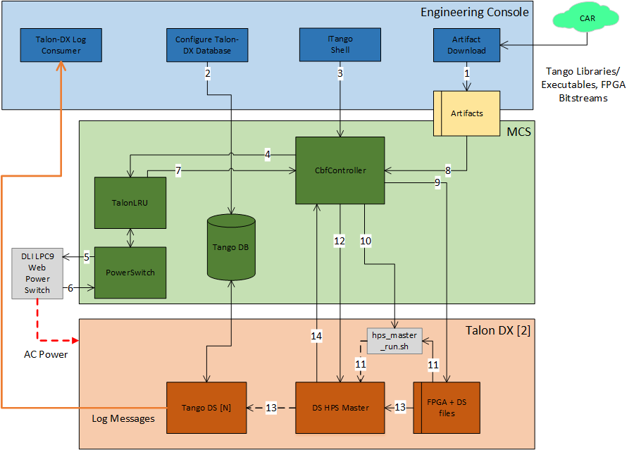
MCS On Command Sequence
Command Sequence
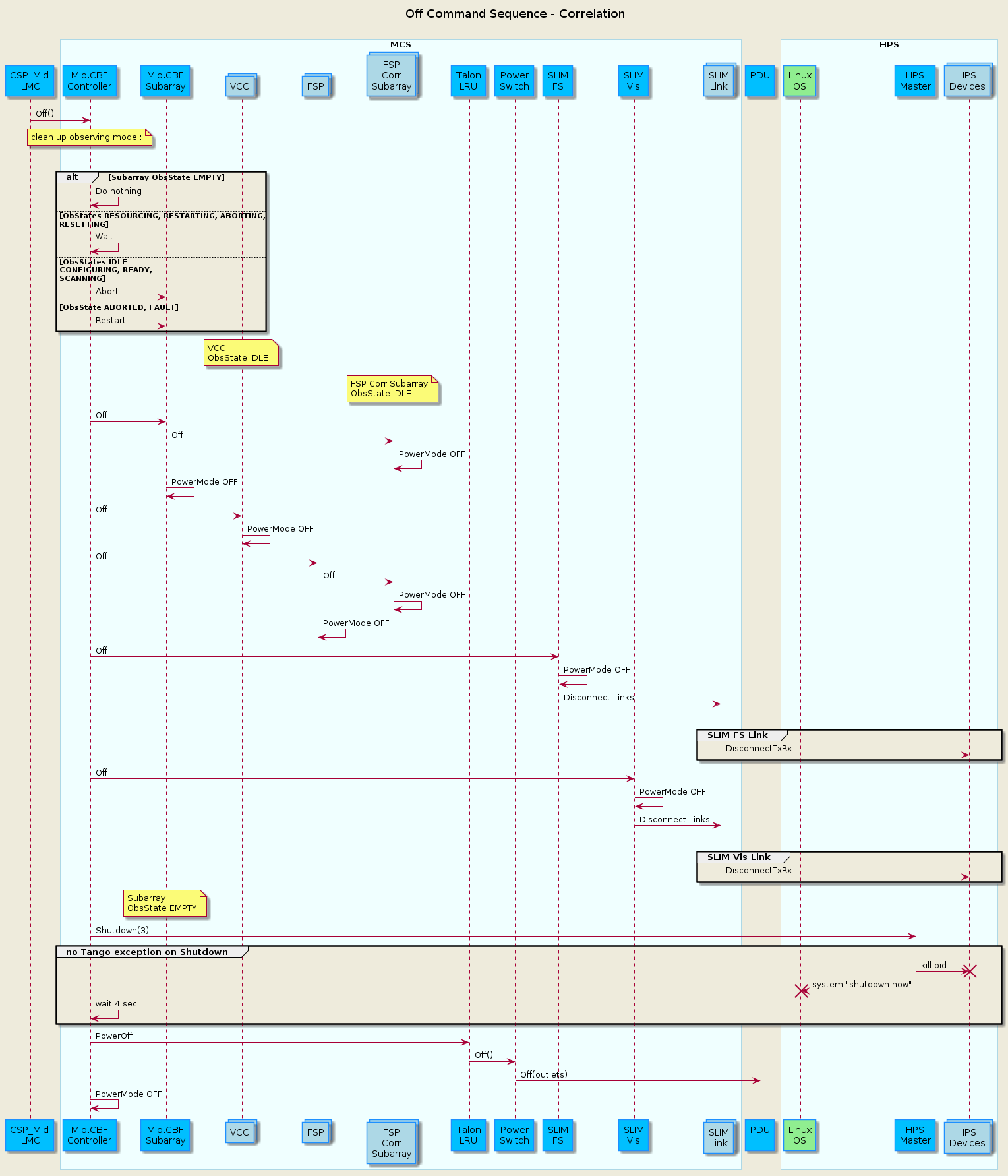
Off Sequence
The sequence diagram below shows the main sequence of calls in MCS when the Off command is called. Return calls are not shown.
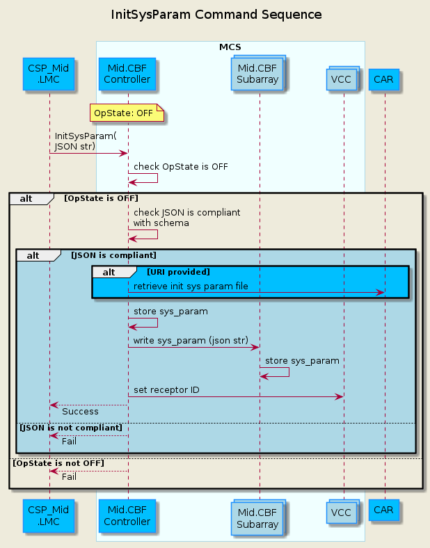
InitSysParam Sequence
The sequence diagram below shows the main sequence of calls in MCS to initialize the system parameters.
Configure Scan Sequence
The sequence diagram below shows the main sequence of calls in MCS to configure a correlation scan. Return calls are not shown.
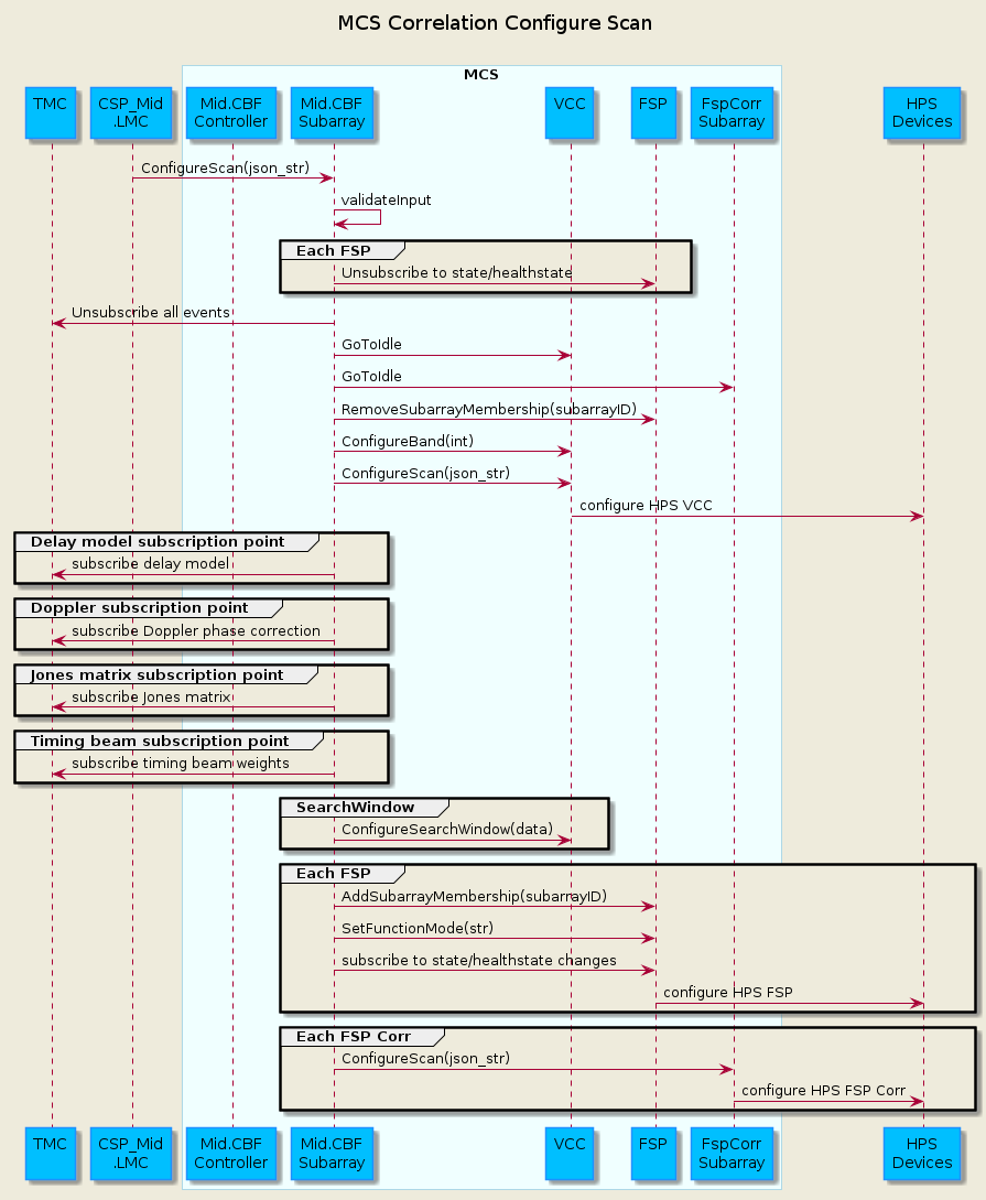
The sequence diagram below shows additional detail for configuration of the VCC for a correlation scan, following the ConfigureScan call from LMC.
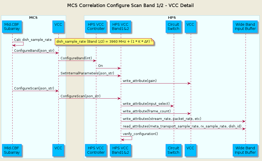
When the Subarray calls ConfigureBand, the jsonstr argument contains:
“frequency_band”
“dish_sample_rate”
“samples_per_frame”
When the Subarray calls ConfigureScan, the jsonstr argument contains:
“config_id”
“frequency_band”
“band_5_tuning”
“frequency_band_offset_stream1”
“frequency_band_offset_stream2”
“rfi_flagging_mask”
“fsp”
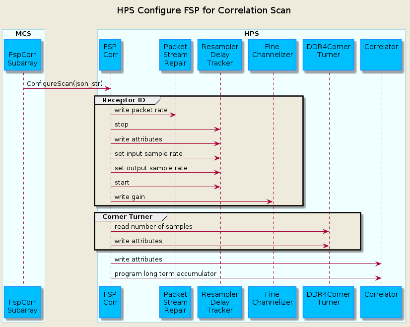
The sequence diagram below shows details of calls to configure a FSP for a correlation scan.
Abort Sequence
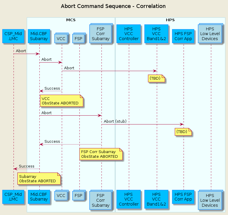
The sequence diagram below shows the main sequence of calls in MCS to Abort from a correlation scan. Return calls are not shown.
ObsReset Sequence
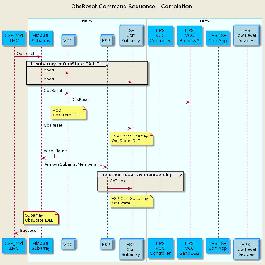
The sequence diagram below shows the main sequence of calls in MCS to return to IDLE via the ObsReset command for a correlation scan. Return calls are not shown.
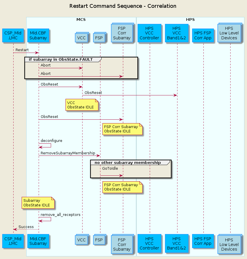
Restart Sequence
The sequence diagram below shows the main sequence of calls in MCS to return to EMPTY via the Restart command for a correlation scan. Return calls are not shown.
Serial Lightweight Interconnect Mesh (SLIM) Interface
Refs: SLIM IP Block, Serial Lightweight Interconnect Mesh (SLIM) Design
The Serial Lightweight Interconnect Mesh (SLIM) provides a streaming packet link between two different FPGAs. At its lowest level, a TX and RX IP block are paired together to transfer packetized data across a high-speed serial link. The SLIM architecture consists of three parts: The HPS DsSlimTxRx device server, which provides an interface to the FPGA IP, the MCS SLIM Links, which establish links between Tx and Rx devices, and finally the top level MCS SLIM Mesh (simply called ‘SLIM’), which bundles links into groups for better organization.
The DsSLIMTX and DsSLIMRx are provided together as a multi-class HPS device server to control and monitor the SLIM Links. To provide a link, each TX device server must connect to a corresponding RX device server, based on the SLIM configuration (see next section).
During a SLIM Link’s initialization, the FQDNs of a Tx and Rx device pair are passed as arguments and device proxies are made to each device. Then the connection is monitored by periodically comparing the idle control words (a 55-bit hash of the Tx or Rx’s FQDN) on either side of the link, checking that the bit-error rate remains below an acceptable threshold, and ensuring that clocks on each side of the link remain in sync. Each link uses an enumerated HealthState attribute to summarize these metrics.
At the top of the SLIM hierarchy, sits the SLIM device (sometimes referred to as the ‘mesh’), which is essentially just a list of SLIM Links. Currently there are two SLIM instances, one for the frequency slice (FS) mesh, and the other for the visibility (Vis) mesh. While each SLIM Link is identical to the rest, they are organized into different mesh instances to differentiate between distinct stages in the signal processing chain. The SLIM device parses the SLIM configuration file (discussed next), and is responsible for spawning the appropriate links. It also rolls up all of the links’ HealthState attributes into a single master HealthState attribute to summarize the status of the entire mesh. If any of the links report a degraded HealthState, the mesh also becomes degraded.
SLIM Configuration
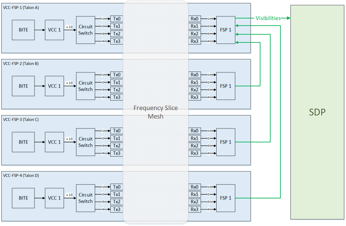
SLIM Interconnections for AA0.5 CBF
SLIM Configuration Sequence
AA0.5 quantities shown.
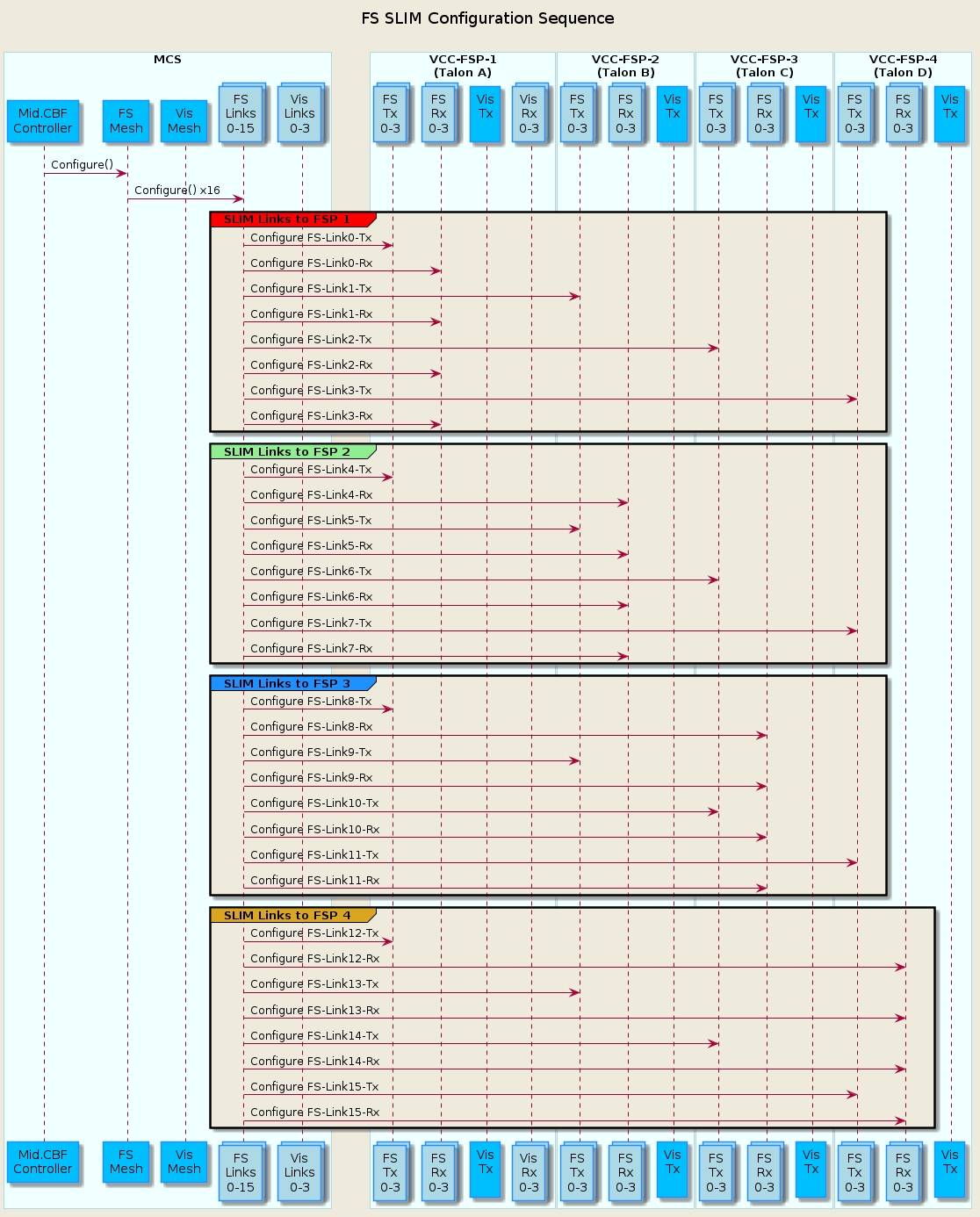
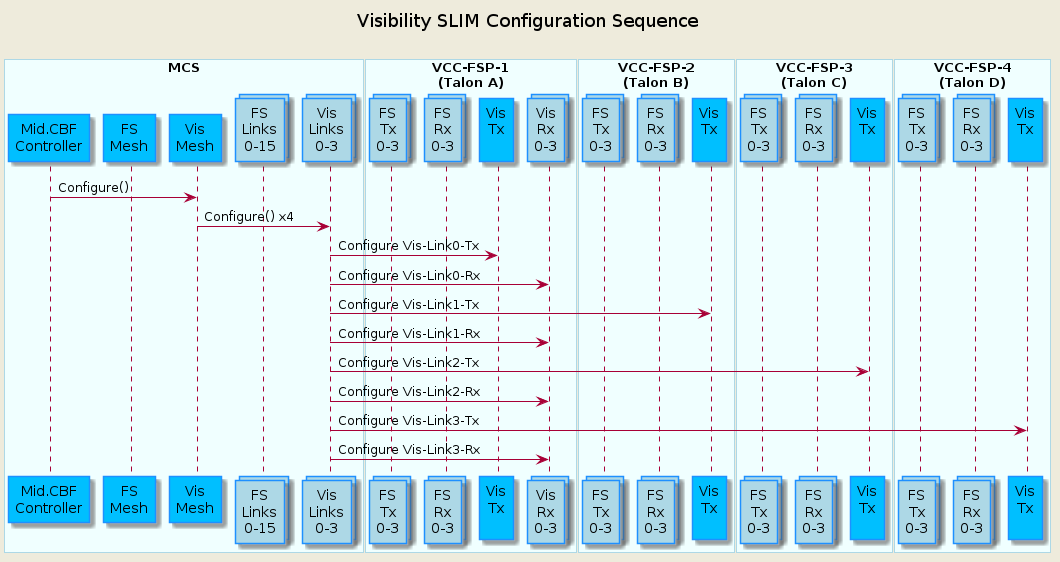
SLIM FS Links Definition Example YAML File
[x] indicates inactive link. Part of the MID CBF AA0.5 Talondx-Config MCS Data Model
links_to_fsp1:
  - talondx-001/slim-tx-rx/fs-tx0 -> talondx-001/slim-tx-rx/fs-rx0
  - talondx-002/slim-tx-rx/fs-tx0 -> talondx-001/slim-tx-rx/fs-rx1
  - talondx-003/slim-tx-rx/fs-tx0 -> talondx-001/slim-tx-rx/fs-rx2
  - talondx-004/slim-tx-rx/fs-tx0 -> talondx-001/slim-tx-rx/fs-rx3
  - talondx-005/slim-tx-rx/fs-tx0 -> talondx-001/slim-tx-rx/fs-rx4 [x]
  - talondx-006/slim-tx-rx/fs-tx0 -> talondx-001/slim-tx-rx/fs-rx5 [x]
  - talondx-007/slim-tx-rx/fs-tx0 -> talondx-001/slim-tx-rx/fs-rx6 [x]
  - talondx-008/slim-tx-rx/fs-tx0 -> talondx-001/slim-tx-rx/fs-rx7 [x]
SLIM Visibility Links Definition Example YAML File
[x] indicates inactive link. Part of the MID CBF AA0.5 Talondx-Config MCS Data Model
links_to_vis1:
  - talondx-001/slim-tx-rx/vis-tx0 -> talondx-001/slim-tx-rx/vis-rx0 [x]
  - talondx-002/slim-tx-rx/vis-tx0 -> talondx-001/slim-tx-rx/vis-rx1 [x]
  - talondx-003/slim-tx-rx/vis-tx0 -> talondx-001/slim-tx-rx/vis-rx2 [x]
  - talondx-004/slim-tx-rx/vis-tx0 -> talondx-001/slim-tx-rx/vis-rx3 [x]
  - talondx-005/slim-tx-rx/vis-tx0 -> talondx-001/slim-tx-rx/vis-rx4 [x]
  - talondx-006/slim-tx-rx/vis-tx0 -> talondx-008/slim-tx-rx/vis-rx0 [x]
  - talondx-007/slim-tx-rx/vis-tx0 -> talondx-008/slim-tx-rx/vis-rx1 [x]
  - talondx-008/slim-tx-rx/vis-tx0 -> talondx-008/slim-tx-rx/vis-rx2 [x]
SLIM Tx / Rx Device Servers (HPS)
Note: See SLIM Tx/Rx Documentation for more details.
SLIM Tx
Ref: tx_slim.tango.json
SLIM Rx Ref: rx_slim.tango.json