Code Element Design Notes
Component Managers
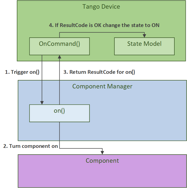
More details about the role of component managers can be found in the SKA Tango Base Documentation. In the Mid.CBF MCS
each component has a Tango device class and a component manager class. The Tango device class updates its state model(s)
(the op_state_model andor obs_state_model). The Tango device class does not directly communicate with its component,
instead it tells its component manager class what to do by calling its methods. The component manager class directly interacts
with its component. Its role is to establish communication with its component and monitor and control it.
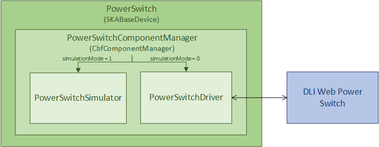
An example of this Tango device and component manager interaction is shown in the diagram below.
Cbf Controller
The CbfController Tango device controls its subordinate Tango devices: Fsp, Vcc, Slim,
CbfSubarray, and TalonLRU. It is responsible for turning these subordinate devices on
and off. The CbfController also initiates the configuration of the Talon-DX boards. The CbfController
device’s OnCommand triggers a call to TalonDxComponentManager.configure_talons, which copies
the device server binaries and FPGA bitstream to the Talon-DX boards, starts the HPS master
device server, and sends the configure command to each DsHpsMaster device.
Cbf Subarray
The CbfSubarray Tango device is used to monitor and control scan operation
of a Mid.CBF receptor subarray. This device receives one configuration per scan,
and a subarray may accept this scan configuration only after being assigned at
least one receptor.
Receptor assignment
Receptor assignment to a subarray is done before configuration for a scan. Receptor assignment is exclusive; receptors assigned to one subarray cannot belong to any other subarray. Up to 197 receptors can be assigned to one subarray; currently, there is only support for 4 receptors.
Scan configuration
Subarrays receive a scan configuration via an ASCII encoded JSON string. The scan configuration is validated for completeness and its parameters implemented as Tango device attributes; the subarray device will then also configure subordinate devices with the relevant parameters, including VCC, FSP and FSP-subarray devices.
Frequency Slice Processor (FSP)
The Fsp Tango device is used for monitoring and control of a Frequency Slice
Processor (FSP) during scan operation. An FSP device can be configured for processing
of one of up to twenty-six frequency slices (depending on observational frequency
band). Additionally, an FSP can be assigned to any number of subarrays with matching
configurations.
Fsp Function Mode
There are four function modes available for FSP scan configuration, each with a corresponding function mode capability and subarray device per FSP; furthermore, each FSP function mode subarray device corresponds to a unique pairing of one FSP with one subarray. Currently, one subarray and four FSPs are supported.
FSP Function Mode Subarray devices:
Correlation (CORR):
FspCorrSubarrayPulsar Search Beamforming (PSS-BF):
FspPssSubarrayPulsar Timing Beamforming (PST-BF):
FspPstSubarrayVLBI Beamforming (VLBI):
FspVlbiSubarray
Mid.Cbf VCC Device Server (VccMulti)
VCC Device
The Vcc Tango device is used to control and monitor the functionality for a
single Talon-DX board that runs VCC functionality. This device communicates with
the top-level VCC device server running on the Talon-DX board to coordinate
setup and processing activites of low-level device servers.
The Vcc device can operated in either simulation mode or not. When in simulation
mode (this is the default), simulator classes are used in place of communication
with the real Talon-DX Tango devices. This allows testing of the MCS without
any connection to the hardware.
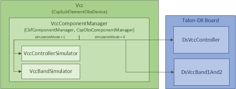
MCS Vcc Device
Serial Lightweight Interconnect Mesh (SLIM) Design
Ref: Serial Lightweight Interconnect Mesh (SLIM) Interface
Slim
The Slim Tango device provides macro control to aggregated subordinate SlimLink Tango devices.
It is responsible for turning the subordinate devices on and off, as well as rolling up
and monitoring important device attributes, such as each link’s HealthState. The Slim
device’s ConfigureCommand triggers a call to SlimComponentManager.configure, which
initializes SlimLink devices as described in a YAML configuration file.
Since the SlimLink component that the Slim device controls is software within MCS, it does not
require a simulator. Whether being tested or not, the Slim device always controls the SlimLink
MCS devices. It should be noted, however, that the Slim device still implements a simulation mode,
and it’s sole purpose is to set the child SlimLink device’s simulation mode. Therefore, simulation mode
is set globally within a mesh and cannot be toggled per link.
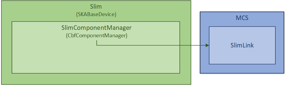
MCS Slim Device
SlimLink
The SlimLink Tango device configures a pair of proxies to slim-tx and slim-rx HPS devices
within the ds-slim-tx-rx device server. It also monitors several of the HPS device’s attributes
that are used to update the SlimLink device’s HealthState attribute. The SlimLink device’s
ConnectTxRxCommand triggers a call to SlimLinkComponentManager.connect_slim_tx_rx, which
initializes the target HPS ds-slim-tx-rx devices by taking them out of serial loopback
mode, syncing idle control words, etc.
The SlimLink device can operate in either simulation mode or not. When in simulation
mode (this is the default), simulator classes are used in place of communication
with the real Talon-DX Tango devices. This allows testing of the MCS without
any connection to the hardware.
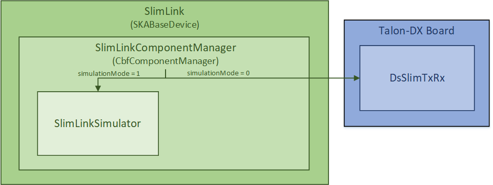
MCS SlimLink Device
Talon LRU
The TalonLRU Tango device handles the monitor and control functionality
for a single Talon LRU. A TalonLRU instance must therefore be created for each LRU.
Currently this device only controls the power to the LRU via a proxy to the PowerSwitch
device.
The operational state of this device always reflects the power state of the LRU.
If at least one of the PDU outlets connected to the LRU is switched on, the state
of the TalonLRU device should be ON. If both outlets are switched off, then the
state should be OFF.
If the state of the outlets is not consistent with the state of the TalonLRU device
when it starts up (or when simulationMode of the PowerSwitch device changes),
the TalonLRU device transitions into a FAULT state. The power outlets must then
be manually switched to the expected startup state via some other method before resetting
the TalonLRU device.
The expected startup state of the device is OFF.
Power Switch
The PowerSwitch Tango device is used to control and monitor the web power switch
that provides power to the Talon LRUs. The current power switch in use is the DLI LPC9 (User Guide).
The power switch has 8 programmable outlets, meaning that it can power up to 4 Talon
LRUs (each LRU has redundant power supplies).
The PowerSwitch device can be operated in either simulation mode or not. When in simulation
mode (this is the default), the PowerSwitchSimulator is used in place of communication with
the real power switch hardware. This allows testing of the MCS with no hardware connected.
When integration testing with the hardware is desired, the simulationMode attribute can
be set to 0. This initializes communication with the real power switch via the PowerSwitchDriver,
and queries the list of outlets in the power switch.
MCS PowerSwitch Device
Important operational notes:
Certain requests to the power switch hardware can take longer than others, hence a timeout of 4 seconds set in the
PowerSwitchDriver. As such, accessing attributes or commands in thePowerSwitchdevice can take longer than the default Tango timeout (3 seconds). AnyDeviceProxyof thePowerSwitchdevice should increase its timeout to 5 seconds to safely complete all requests (both successful and unsuccessful) before the Tango timeout. This can be done usingpwr_dev_proxy.set_timeout_millis(5000), assumingpwr_dev_proxyis aDeviceProxyto thePowerSwitchdevice.Although the DLI LPC9 claims to support up to 8 concurrent clients, testing has shown a significant slow down in response time when more than one request has been sent to the power switch. As such, all communication with the power switch should be kept sequential. Currently the
PowerSwitchDriverdoes not ensure this. If thePowerSwitchdevice is ever changed to handle requests asynchronously, thePowerSwitchDrivershould also be updated to only process one request at a time.
Talon DX Log Consumer
The Talon DX Log Consumer is a Tango device intended to run on the host machine that connects to the Talon-DX boards. This Tango device is set up as a default logging target for all the Tango device servers running on the HPS of each Talon-DX board. When the HPS device servers output logs via the Tango Logging Service, the logs get transmitted to this log consumer device where they get converted to the SKA logging format and output once again via the SKA logging framework. In this way logs from the Talon-DX boards can be aggregated in once place and eventually shipped to the Elastic framework in the same way as logs from the Mid CBF Monitor and Control Software (MCS).
Note: more instances of the device may be created to provide enough bandwidth for all the HPS device servers.
Connecting from HPS DS to the Log Consumer
The Talon-DX boards connect to the host machine (currently known as the development server) over
a single Ethernet connection. The IP address of the development server on this connection is
169.254.100.88 and all outgoing traffic from the Talon-DX boards must be addressed to this IP.
When the log consumer starts up on the development server, the OmniORB end point (IP address and port) it is assigned
is local to the development server (i.e. IP address 142.73.34.173, arbitrary port). Since the Talon
boards are unable to connect to this IP address. we need to manually publish a different
endpoint when starting up the log consumer that is visible to the HPS devices.
The following ORB arguments are used (see the make target talondx-log-consumer):
-ORBendPointPublish giop:tcp:169.254.100.88:60721: Exposes this IP address and port to all clients of this Tango device. When the HPS device servers contact the database to get the network information of the log consumer, this is the IP address and port that is returned. The IP address matches that of the Ethernet connection to the development server, allowing the HPS device servers to direct their messages across that interface.-ORBendPoint giop:tcp:142.73.34.173:60721: Assigns the IP address and port that the log consumer device is actually running on. This needs to be manually assigned since an iptables mapping rule was created on the development server to route any TCP traffic coming in on169.254.100.88:60721to142.73.34.173:60721.
Some important notes:
Due to the end point publishing, no Tango devices running on the development server will be able to connect to the log consumer (including being able to configure the device from Jive). This is because the published IP address is not accessible on the development server. There may be a way to publish multiple endpoints, but this needs further investigation.
If the log consumer device cannot be started due to an OmniORB exception saying that the end point cannot be created, it is possible that the
142.73.34.173needs to change to something else. It is not yet clear why this can happen. To change it, do the following:Remove the ORB arguments from the
talondx-log-consumermake target, and then start the log consumer.Open up Jive and look at what IP address is automatically assigned to the log consumer device. This is the IP address that we now need to use for the endpoint.
Find the iptables rule that maps
169.254.100.88:60721to142.73.34.173:60721, and change it to the new IP address.Add the ORB arguments back in, using the correct IP address for the end point.