MccsTile general overview
This page gives a general brief overview to the architecture of the MccsTile.
Tango Tile Device Construction
During deployment MccsTile is constructed with a platform specific configuration defined by helm see https://developer.skao.int/projects/ska-low-mccs-spshw/en/latest/guide/deploy.html. The MccsTile contructs a TileComponentManager using information from this configuration. This configuration includes a simulation_mode flag. When simulation_mode is TRUE a TileSimulator will be constructed and used as the backend, when False a ska_low_sps_tpm_api.Tile object will be created to interface with the hardware as a backend.
Tile brief architecture
The MccsTile inherits from the SkaTangoBase class, this is the interface for TANGO control. Information and instructions are sent to the hardware using this interface via a ‘TileComponentManager’. The ‘TileComponentManager’ is a ‘PollingComponentManager’ and will poll requests on the backend system, the decision of what to poll is determined by the ‘TileRequestProvider’.

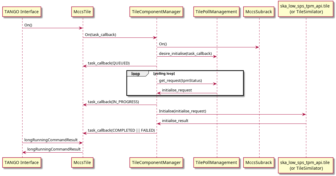
Tile On sequence
The “On” command will bring the MccsTile to ‘PowerState.ON https://developer.skao.int/projects/ska-control-model/en/latest/power_state.html This will involve sending the On command to the MccsSubrack to deliver power then executing the initialise command to the TPM as soon as it is connectable. If a global reference time has been specified, the acquistion is also started, using the specified time as a reference for the internal timestamp registers.
For more information about how the Tile On command fits into the power sequence see https://developer.skao.int/projects/ska-low-mccs-spshw/en/latest/reference/power.html
Tile operation state
See https://developer.skao.int/projects/ska-control-model/en/stable/op_state.html.
Information specific to Tile is provided below:
UNKNOWN: the control system is monitoring (or at least trying to monitor) the system under control, but is unable to determine its state. this will occur when we cannot connect with the TPM and the MccsSubrack is reporting its ports power UNKNOWN.
OFF: the control system is monitoring the system under control, which is powered off. This will occur when MccsSubrack says the port is NO_SUPPLY or OFF, and we are NOT connected with the TPM.
STANDBY: Not implemented in Tile.
ON: The control system is monitoring the system under control, which is turned on. This will occur when we are connected and communicating with the TPM.
FAULT: The Tile will be in state FAULT under inconsistent state. Currently if we can connect with the TPM but the MccsSubrack is reporting a inconsistent state (i.e not ON), we are in FAULT state.
Tile provides a more detailed state in the attribute ‘tileProgrammingState’. This may take the values:
Unknown: the TPM is in UNKNOWN power state
Off: the TPM is in OFF power state
Unconnected: the subrack is providing power to the TPM but no connection has been established
NotProgrammed: The TPM is connected but the FPGAs have not been programmed
Programmed: The TPM is programmed but not initialised
Initialised: The TPM has been initialised, the internal PPS is aligned but acquisition has not been started.
Synchronised: The TPM has been initialised and the data stream has been started and synchronised. Internal timestamps are valid.
The TPM must be in Synchronised state to be usable for observations. All these steps are automatically executed when turning on a tile, as part of the On() command, or in the Initialise() command. The last step (synchronisation) is executed automatically if a global reference time, needed for synchronisation, has been specified, otherwise it has to be executed separately with the command StartAcquisition()
Synchronization Procedure
The main timing reference for the TPM is the 10 MHz clock. This is used to generate a system clock at 100 MHz, which in turn generates a 200 MHz processing clock and a 800 MHz sampling clock.
The PPS signal is resampled at 100 MHz and in turn this is used to correctly label samples from the ADC. The PPS signal must be stable enough to correctly identify the 100 MHz transition which is used internally as a PPS edge. The MccsTile attribute ppsDelayCorrection is used to internally shift the PPS signal, in units of 1.25 ns, in order to avoid metastability problems and to unambiguously define the 100 MHz transition with a “reasonable” relative jitter between the two signals. This delay can be slightly adjusted by the PPS synchronisation hardware, with the actual value returned in the ppsDelay attribute. At each active edge, the alignment of the internal PPS is checked, to detect cycle jumps.
The 100 MHz clock is used to generate an internal version of the PPS, and tis is counted in a second counter. The external PPS is used to synchronise this internal signal, during TPM initialisation. The second counter is initialised to the current Unix time, during initialisation, and is available as the fpgaTime attribute. Leap seconds are not yet managed by the software. As this synchronisation is rather simple, it can be managed by software. The MccsTile device wites the current Unix time in the hardware counter around the center of a second. Unix time is determined by NTP, with respect to the telescope NTP server.
During initialisation the ADC links are synchronised and aligned, and generate a continuous stream of samples, aligned with the internal clock. Data processing is not started. Internal high accuracy timing is determined by conuting samples, or group of samples (frames), from a specific Unix time (reference time). This time must be the same for all TPMs in the telescope, and is given by the globalReferenceTime attribute. The StartAcquisition method is used to start the actual signal processing chain, at a specific Unix time (in the future), using the globalReferenceTime (in the past) specified in the attribute or as a command parameter.
In short, there are two ways to synchronise a tile
(preferred): Specify the desired reference time in the globalReferenceTime attribute, and initialise the TPM by turning it On or with the Initialise command.
Initialise the TPM and then start the acquisition using the StartAcquisition command. This must specify a common reference time
Frames are composed of 864 ADC samples, starting at globalReferenceTime, and corresponding to one channelised sample (1.08 microseconds sampling period). All internal commands to the TPM are specified at hardware level in units of 256 frames (276.48 microseconds). These units are used also to timestamp SPEAD packets to the DAQ system, and is indicated in the software/firmware as a timestamp. As the frame period does not divide exactly one second, the StartAcquisition command does not start the acquisition at a second boundary, but at the correct time to align frames with the common (virtual) frame phase.
SPEAD packets to CBF contain 2048 channelised samples (2.21184 ms). The number of packets between TAI 2000 epoch and the globalReferenceTime is added to the packet counter in the SPEAD header to mark the start time of the packet. Representing time using an integer number of packets imposes that the globalReferenceTime must be at a multiple of 864 seconds since TAI 2000. This is enforced in the software, and the attribute value is corrected to represent the actual used value. Another important limitation si due to the fact that the timestamp counter is currently sized at 32 bits, limiting the maximum representable time at 13.74 days after the globalReferenceTime. This implies that the TPMS must be reinitialised and synchronised at most every 13 days.
Firmware Thresholds – Engineering Mode Attributes
Overview
Firmware thresholds are attributes which are writeable only in EngineeringMode, to configure and validate firmware-level safety and operational limits for voltage, current, and temperature.
The following attributes are available:
firmwareVoltageThresholdsfirmwareCurrentThresholdsfirmwareTemperatureThresholds
These attributes represent the threshold values read directly from the firmware and become available after connecting to the TPM (Tile Processing Module).
Behavior and Lifecycle
When interacting with firmware thresholds, the following operational flow applies:
Writing a Threshold
When a threshold is written:
The value is first written to the firmware.
If the firmware write succeeds, the database (DB) is updated to reflect the desired value.
An automatic comparison between the DB and firmware values is then performed.
Fault Detection
If any mismatch between the DB and firmware values is detected, the device will enter a fault state. The fault state ensures that configuration discrepancies between stored expectations and actual firmware conditions are highlighted immediately.
Diagnosing Configuration Faults
The faultreport attribute provides detailed diagnostic information for configuration
mismatches. A typical fault report looks like this:
{
  "firmware_configuration_status":
  "Configuration mismatch: [voltages.MGT_AVCC_min_alarm_threshold] DB=0.829, HW=0.828;
   [voltages.MGT_AVCC_max_alarm_threshold] DB=0.944, HW=0.945;
   [voltages.MGT_AVTT_min_alarm_threshold] DB=1.105, HW=1.104;
   [voltages.MGT_AVTT_max_alarm_threshold] DB=1.25, HW=1.26"
}
This example indicates that the database (DB) and hardware (HW) values are not identical, resulting in a firmware configuration fault.
Clearing Configuration Faults
If you wish to clear the database values without performing a write to firmware,
you can set the desired thresholds to "Undefined". This is a special keyword that
instructs the system not to compare firmware values for these entries.
Example:
tile.firmwareVoltageThresholds = json.dumps({
    "MGT_AVCC_min_alarm_threshold": "Undefined",
    "MGT_AVCC_max_alarm_threshold": "Undefined",
    "MGT_AVTT_min_alarm_threshold": "Undefined",
    "MGT_AVTT_max_alarm_threshold": "Undefined"
})
After applying this, any mismatch faults related to these thresholds will be cleared.
Persistence and Power Cycle Behavior
Database Persistence
The database values are persisted and restored on startup. A pod bounce or device restart will not alter previously written threshold values.
Firmware Reset on Power Cycle
A power cycle resets all firmware thresholds to default BIOS-defined values. If the database contains overridden thresholds, this will result in a configuration mismatch fault upon reconnect.
To resolve this:
Reapply the desired threshold overrides, or
Set the thresholds to
"Undefined"to prevent comparison until the configuration is updated.