Power management in MCCS
Hardware power modes
SKA hardware may support up to three power modes:
ON: the hardware is powered on and fully operational. This mode is supported by all SKA hardware.
OFF: the hardware is powered off. Generally we would expect all hardware to be able to be turned off. There may be special cases, however, where this is not supported. For example, an externally managed cluster can be turned off, but the MCCS interface to it might only allow for submission and monitoring of jobs. Thus it cannot be turned off from the MCCS point of view.
STANDBY: the hardware is in a low-power standby mode. Such a mode is important in two cases:
where powering up a subsystem with many devices, it is important to limit the inrush current. This is achieved by powering up devices into a standby mode that uses no more than 5% of their nominal power; then carefully orchestrating transitions to full power.
where powering up a device from off could take a long time (perhaps several minutes). Such devices may instead be powered up into standby mode, in which power consumption is low, but the time to fully power on the hardware is short (a couple of seconds).
Standby mode is not supported by all hardware; indeed there may be very few hardware devices that support it.
Power mode breakdown
Generally speaking, one cannot tell a hardware device to turn itself off; for once it is off, it loses the ability to turn itself on again. Instead, power to a device is controlled by some upstream device. For example, power to a TPM is controlled by the subrack in which that TPM is installed. Standby mode, however, is controlled by the device itself. Thus, implementation of the three power modes breaks down into:
OFF: tell the upstream device (e.g. subrack) to deny power to the device (e.g. TPM)
STANDBY: tell the upstream device to supply power to the device, then tell the device itself to go into standby mode
ON: tell the upstream device to supply power to the device, then tell the device itself to go fully operational
Power flow
Map
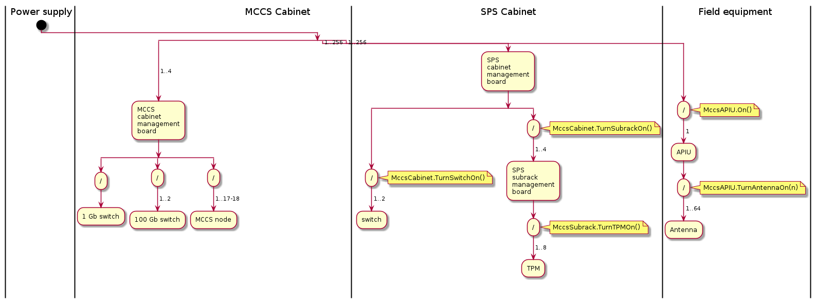
The activity diagram below shows the flow of power through the MCCS system; i.e. cabling, essentially. The (/) points are switch points at which the power can be turned on/off. These switch points are annotated with the Tango device commands that drive the switch.
Note: this diagram will evolve over time.
Startup sequence
Boot-up
When power is first applied to MCCS, the following minimal bootup sequence is followed:
Power is applied to all cabinets. All the cabinet management boards come on, as they are the primary control points for the cabinet subsystems. Switches and subelements for the SPS cabinets are configured to remain off, as are the subelements for all but one of the MCCS cabinets.
Power is applied to the APIUs in the field nodes. All the antennas are configured to remain off.
The cabinet management board for the MCCS cabinet that houses the MCCS controller node is configured to start up the cabinet’s 1Gb network switch and the MCCS controller node.
The 1Gb network switch powers up
The MCCS controller node boots up.
The kubernetes cluster is started.
A minimum chart is deployed, containing just the tango subsystem and the MCCS Controller Tango device.
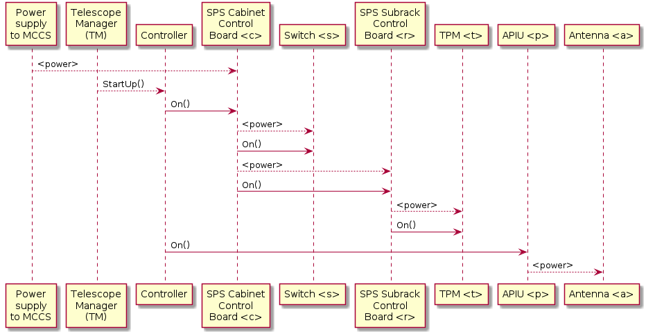
Power-on
When TM sends the MCCS Controller the Startup command, the MCCS Controller must start up:
the rest of MCCS
the SPS subrack management boards and switches
the SPS TPMs
the field equipment
Prototype status
In the current prototype implementation, all of MCCS is deployed immediately on startup, so that when TM sends the MCCS Controller the Startup command, it need only start up the SPS cabinets and field equipment.
Self Shutdown
The MccsTile has the ability to modify the ALARM and WARNING thresholds on attributes.
Certain attributes are configured to shutdown on ALARM. Currently these are:
boardTemperature
fpga1Temperature
fpga2Temperature
The following snippet shows how you can configure the thresholds.
thresholds = {
    "boardTemperature" : {
        "max_alarm": "79"
        "min_alarm": "25"
        "max_warning": "74"
        "min_warning": "27"
        },
    }
tile_proxy.SetAttributeThresholds(json.dumps(thresholds))
# To see the max_alarm value.
print(tile_device.get_attribute_config(attribute).max_alarm)
    ...