Tango SPS Station attributes and methods
The SpsStation is responsible for controlling and managing the SPS hardware resources for a station. It is part of the device group monitoring and controlling a SPS cabinet. The (tentative) class diagram for these classes is shown in the figure below:
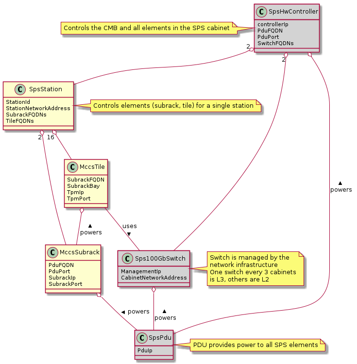
Devices marked in gray are not yet designed. Class names and other details depend on the Sps Cabinet physical implementation.
Tango SpsStation Device Construction
Important parameters (Tango properties) for initialisation are:
StationId: The numeric ID for the station, identifies the station in the telescope. Integer in the range 1 to 512
TileFQDNs List of FQDNs for the tile devices composing the station. Tile order is important, attributes and command parameters related to antennas are indexed assuming 16 antennas per tile, in the order given here. Up to 16 tiles can be specified. In a test environment, less than 16 tiles can be used.
SubrackFQDNs FQDNs of the subrack devices. Each subrack hosts up to 8 tiles. Mapping of tiles to hosting subracks is performed in the MccsTile device, the Station only control subrack power state and checks for subrack device health.
StationNetworkAddress The net address for the start of the station address block reserved for data. The station assigns network addresses to the tile 40G ports using this address and the Tile sequence number.
The device construction instantiates device proxies for the managed MccsTile and MccsSubrack devices. When the Station is put Online, these proxies connect to the associated devices and monitor their state.
Station initialisation is performed by bringing all hardware elements online. Then the semi-static attributes are specified. Then the On() or Initialise() commands are issued. Initialise() is used if the Station is already On, and resets the station status to Initialised. When all the stations in the telescope are correctly initialised, proper operation is started using the StartAcquisition command.
Tango SpsStation device attributes
Attributes for the SpsStation are used to specify semi-static initialisation parameters, before issunig the On() or Initialise() command, and to monitor the Station status.
This is an initial list of implemented attributes, to be extended and modified.
Semi-static parameters
These parameters are set during initialisation, and typically are not changed until the next initialisation. Changes in these parameters should not occur while a scan is active. Parameters are stored locally and, if the Tile is not in ON state (TileProgrammingState Initialised or Synchronised), these are used to program the Tile at the next initialisation. If TileProgrammingState is Initialised or Synchronised, the attribute is forwarded to the Tiles.
staticTimeDelays Introduces a fixed delay, as an integer number of samples, in each signal. This is used to compensate for cable mismatches, and roughly align the antenna signals for zenith.
Argument: array of up to 512 (32 per tile) float values, in nanoseconds. Rounded to nearest integer sample (1.25 ns), range +/-154 ns. (123 samples). Positive delay adds delay to the signal stream
channeliserRounding Channeliser output is re-quantised to 12 bits, to allow signal processing using small integer arithmetics. As the input signal has a steep spectrum, it is necessary to equalise the frequency channels, in order not to loose significance. Rescaling is performed by dropping 0-7 least sigificant bits, and clipping the resulting value to 12 bits. A truncation of 0 means just clipping the channelizer output (max. sensitivity), a truncation of 7 rescales the channelizer output by 1/128 (min. sensitivity). A value of 4 is adequate for a flat input spectrum.
Argument: a linear array of 512 elements, one per physical channel. The same value is applied to the corresponding channel for all inputs. If only one value is specified, it is extended to 512 values (same value for all channels).
cspRounding Beamformed samples are re-quantised to 8 bits to be sent to CSP. As for the channeliser truncation, this is performed by discarding LS bits, rounding and clipping the resulting value to 8 bits.
Argument: array of 384 integers, with one value per beamformed channel. Only a single value, for all channels, is available in the current firmware (uses first element in array).
preaduLevels Attenuator setting for PreADU inputs.
Argument: One (int) value per input, range 0 to 31, 32 values per tile, up to 512 per station.
Monitor of configuration parameters
These attributes are read only, and are used to check the values of parameters set using specific commands.
beamformerTable
Return an array of 7 elements for each group of 8 configured channels. Each “row” specifies
first physical channel in group of 8 channes. Must be even
beam number. Range 0 to 47 (0 to 7 for current firmware)
subarray ID. Range 1 to 16
subarray_logical_channel. Logical channel in the channels assigned to the subarray
subarray_beam_id.
substation_id.
aperture_id. The element is not used anywhere (aperture is identified by station and substation IDs) and could be deleted in the future.
cspIngestAddress:
cspIngestPort
fortyGbNetworkAddress
Other monitor attributes
testGeneratorActive Bool, True if at least one of the TPM inputs is being sourced by the internal test signal generator.
isProgrammed: Boolean, True if the FPGAs are programmed.
isBeamformerRunning: Bool, True if the station beamformer is running. The tile beamformer is always running after the StartAcquisition command.
tileProgrammingState: a string describing the programing state of the TPM. It may assume one of the values:
Unknown: the state cannot be determined
Off: the tile is powered off
Unconnected: the connection with the tile is not established
NotProgrammed: the TPM is powered on but the FPGAs have not been programmed
Programmed: The TPM is on, FPGAs have been programmed but the firmware has not been initialised.
Initialised: The TPM firmware modules have been initialised. The 40G interfaces are up and running, ARP protocol has set the interface MAC addresses, the internal PPS is synchronsed with the distributed PPS signal, the internal coarse clock is syncrhonous with UTC
Synchronised: The ADCs have been synchronised. The internal timestamp counter is synchronised among TPMs, and can be used to infer sample timeadcPower: RMS level of the signals in the station inputs. Each consecutive pair of values refer to the X and Y polarisations of one antenna. 32 consecutive values refer to the antennas processed by one tile, in tile order. In ADC units.
Health state attributes
These attributes collect and summarize the corresponding attributes in the underlying hardware devices. For numeric parameters, the minimum, average and maximum value are reported. For boolean parameters the result is True (OK) if this holds for all monitored devices.
boardTemperaturesSummary
fpgaTemperaturesSummary
ppsDelaySummary
sysrefPresentSummary
pllLockedSummary
ppsPresentSummary
clockPresentSummary
fortyGbNetworkErrors
Tango SpsStation Device Commands
General power and initialisation commands
These commands change the power state of the Station, and are implemented as long running.
On: All the controlled devices which are in Online admin mode are turned on. When these have all reached the On status, the Initialise command is performed. Station status is On when all tiles are properly initialised (but not synced)
Off: All the controlled devices are turned off.
Standby: All subracks are turned On, or left in On state. All Tiles are turned Off. This command is not yet implemented.
Initialise: All Tiles are programed using the stored semi-static attributes. The Tile 40G interfaces are programmed to implement the beamforming SPS chain, with the last tile sending packets to the designated CSP ingest IP/port. Tile coarse synchronization (to PPS) is cross checked. Progress is reported via the task callback at the following intervals:
Tile source IPs are set - 5%
Tiles reinitialised - incrementally up to 65% as tiles reach synchronised state
Tile parameters initialised - 70%
Station initialised - 75%
ARP tables ready - 85%
Data streams routed to DAQs - 90%
Station synchronisation checked - 95%
Beamformer started - complete
StartAcquisition: ADC acquisition is started synchronously for all tiles. This command must be coordinated (same sync time) for all stations in the telescope.
Station configuration commands
These commands are used to set some parameters in the Station configuration, before initialisation. These can be used (with care) after initialisation. Most parameters are set using attributes, these commands mainly relate with network configuration, which is better managed using structured
SetCspIngest: set the CSP ingest IP and port. These attributes can be read back using cspIngestIp and cspIngestPort attributes.
Parameter: a json dictionary with optional keywords:
destination_ip - (string) Destination IP for beamformed sample data stream.
source_port - (int) Source port for beamformed sample data stream.
destination_port - (int) Destination port for beamformed sample data stream.
SetLmcDownload: set the destination IP address and port, and the interface used (1Gb control or 40Gb data) to send LMC sample spigot packets to the DAC subsystem.
Parameter: a json dictionary with optional keywords:
mode - (string) 1G or 10G (Mandatory) (use 10G for 40G link). Note that the bandwidth of the 1G link is insufficient if more than one tile is sending data.
payload_length - (int) SPEAD payload length for channel data. Default is 1024 bytes for 1G interface and 8192 bytes for 40G interface.
destination_ip - (string) Destination IP. Is mandatory for 40G link, not required for 1G link (will use the IP address of the MCCS tile control node).
source_port - (int) Source port for sample data streams
destination_port - (int) Destination port for sample data streams
SetLmIntegratedcDownload: Set the destination IP address and port, and the interface used (1Gb control or 40Gb data) to send LMC integrated data packets (spectra) to the DAC subsystem.
Parameter: a json dictionary with optional keywords:
mode - (string) 1G or 10G (Mandatory)
channel_payload_length - (int) SPEAD payload length for integrated channel data
beam_payload_length - (int) SPEAD payload length for integrated beam data
destination_ip - (string) Destination IP. Same IP and port is used for LMC and integrated LMC, so values should be specified only in one of SetLmcDownload and SetLmcIntegratedDownload. Last specified overrides IP and port for both.
source_port - (int) Source port for integrated data streams
destination_port - (int) Destination port for integrated data streams
Scan configuration commands
These commands are used to specify the low level configuration. These basically map to the corresponding MccsTile commands, with the SpsStation broadcasting them to the affected tiles. Detailed description will be performed when these commands will be implemented.
SetBeamFormerRegions Specifies Tile Beamformer configuration in terms of blocks of contiguous channels. It is retained for compatibility with AAVS, where it was used to specify a single observing band, but is deprecated in favour of SetBeamformerTable. In this command channels are internally allocated, so this does not allow multiple subarrays or subarray beam, where channels are allocated externally to the station.
region_array is defined as a flattened 2D array, for a maximum of 48 regions. Total number of channels must be <= 384. Each region is defined by 8 consecutive values:
start_channel - (int) region starting channel, must be even in range 0 to 510
num_channels - (int) size of the region, must be a multiple of 8
beam_index - (int) beam used for this region with range 0 to 47
subarray_id - (int) Subarray
subarray_logical_channel - (int) logical channel # in the subarray
subarray_beam_id - (int) ID of the subarray beam
substation_id - (int) Substation
aperture_id: ID of the aperture (station*100+substation?)
SetBeamformerTable Specifies Tile Bemformer configuration in terms of groups of 8 consecutive channels. Parameter is a flattened 2D array, for a maximum of 48 entries (7*48 values). Each entry corresponds to 8 consecutive frequency channels. This is equivalent to SetBeamformerRegions, with a different way to specify the bandwidth of each spectral region. Input is consistent with the beamformerTable attribute. The table can be updated for specific channel blocks without affecting observation in remaining, unchanged, blocks.
Parameter: list of regions. Each region is defined by 7 values:
start_channel - (int) region starting channel, must be even in range 0 to 510
beam_index - (int) beam used for this region with range 0 to 47. Current firmware is limited to 8 beams (0 to 7)
subarray_id - (int) Subarray. Range 1 to 16.
subarray_logical_channel - (int) logical channel # in the subarray
subarray_beam_id - (int) ID of the subarray beam
substation_id - (int) Substation
aperture_id: ID of the aperture (station*100+substation?)
LoadCalibrationCoefficients: Specify the calibration coefficients for one antenna. Calibration coefficients are given as 8 consecutive values per beamformer frequency channel, in the order defined by the beamformer table. Each block represents a inverse Jones complex matrix.
parameter: a float array of up to 384*8+1 elements. First element indicates the antenna (range 0 to 511). Remaining elements represent inverse Jones matrices for each frequency channel.
LoadCalibrationCoefficientsForChannels: Load cal coefficients for all antennas and a set of contiguous channels.
parameter: float array with (2048 x n_channels) + 1 elements. First element indicates the first beamformer channel for which coefficients are provided, each subsequent block of 2048 channels is interpreted as a ([256,4], complex) array of coefficients for 256 antennas, 2x2 Jones matrix, real+imaginary, for one frequency channel. Unspecified channels are not changed.
ApplyCalibration: Apply the calibration coefficients for all channels and antennas. The applied coefficients are copied back in the calibration array, so successive operations of loadCalibrationCefficients + ApplyCalibration may be used to separately update individual subset of channels (beams).
Parameter: string specifying the time for applying the delays. Formatted as ISO 8691 UTC time.
LoadPointingDelays: Load delays for all antennas and a single beam. Delays are specified one beam at a time, typically by a StationBeam device, and updated together at a specific time by the ApplyPointingDelay command.
Parameter: json string with an array of up to 513 elements (float).
First element specifies the beam index. Range 0-47, 0-7 in the current firmware version.
Each subsequent couple of values specify the delay in seconds and the delay rate in seconds/second for one antenna, in antenna order.
ApplyPointingDelays: Apply all delays specified by LoadPointingDelays commands at a specific time.
Parameter: string specifying the time for applying the delays. Formatted as ISO 8691 UTC time. At this time delays for all beams are set to the specified value, and begin to change at the specified delay rate.
StartBeamformer: Start the station beamformer. In current version, all beams are started together. In future firmware, the ability of starting and stopping individual beams will be added. The Parameters are specified with a json string with the keywords:
start_time: ISO-8691 formatted UTC time. This is rounded up to a multiple of 2048 channelized samples since the sync time (set by StartAcquisition). The Station begin to send beamformed samples to the CSP starting at this time.
duration: Scan duration in seconds. If omitted or negative (-1) scan lasts forever. Duration is rounded down to a multiple of 2048 channelized samples (2.22184 ms).
channel_groups: list of channel groups to which the command applies. Bitmask with one bit for each group of 8 beamformer channels, default applies to all channels. The current firmware supports only the default (start all channels)
scan_id: ID for the scan which is started. Long integer, truncated to 48 bits, default to 0. Currently not supported by firmware.
StopBeamformer: Stop the station sending beamformed data to CSP for all channel groups (all beams).
StopBeamformerForChannels: Stop the station sending beamformed data to CSP for the specified channel groups.
Parameter: Channel groups to which the command applies. List with one integer element (range 0 to 47) for each group of 8 beamformer channels.
BeamformerRunningForChannels: Returns the beamformer running state for the specified channel groups. Returns True if all tiles have at least one channel group with running beamformer.
Parameter: Channel groups to which the command applies. List with one integer element (range 0 to 47) for each group of 8 beamformer channels.