Design Notes
This document elaborates key concepts for the developer’s understanding of the SKA Mid Telescope Correlator and Beamformer, or Mid.CBF, Monitoring and Control System, referred to herein as MCS. The MCS is the highest level of Mid.CBF signal-processing control software, and is a system of Tango devices deployed to a control server node in the SKA Kubernetes (k8s) cluster.
The full AA* deployment of MCS will comprise 162 k8s pods, with each pod running
1 Tango device server, and will have a total of 1890 Tango devices. The distribution
is as follows, with x denoting variable indices in pod names (note that device
server names typically match the device class names):
1
ds-mid-cbf-controller-0-0pod containing 1CbfControllerdevice server running 1 instance ofCbfController16
ds-mid-cbf-subarray-xx-0pods each containing 1CbfSubarraydevice server running 1 instance ofCbfSubarray32
ds-mid-cbf-vcc-unit-xx-0pods each containing 1VccUnitdevice server running 1 instance ofVccUnit27
ds-mid-cbf-fsp-unit-xx-0pods each containing 1FspUnitdevice server running 1 instance ofFspUnit27
ds-mid-cbf-fsp-multi-xx-0pods each containing 1FspMultidevice server running 1 instance ofFsp, 16 instances ofFspCorrSubarray, 16 instances ofFspPstSubarray, 16 instances ofFspPssSubarrayand 16 instances ofFspVlbiSubarray59
ds-mid-cbf-network-switch-xx-0pods each containing 1NetworkSwitchdevice server running 1 instance ofNetworkSwitch
Controller
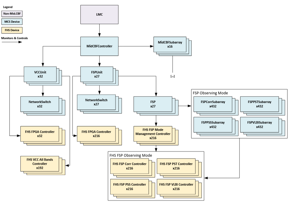
MCS Monitoring & Control - Controller View
The CbfController class implements operational control of the Mid.CBF; deployed
in a single instance that is referred to as the “controller,” it is one of two primary
external interfaces to the Mid.CBF alongside CbfSubarray.
The controller directly monitors and controls the CbfSubarray, VccUnit and
FspUnit MCS devices, setting their communications online and offline via its
adminMode attribute, aggregating the health state and status of the
entire Mid.CBF via its healthState and healthInfo attributes, and
initializing system-wide parameters via its InitSysParam command. In particular,
the InitSysParam command is used to provide a mapping between Mid.CBF dish IDs
and VCC IDs, a translation which is further discussed in subsequent sections.
ResourceStatus Attribute
resourceStatus is an attribute in CbfController that provides
a ResourceStatus report for an operator to decide whether the VCC and
FSP resources are “available” for a specific purpose.
When resourceStatus is called, CbfController will pull and gather status
details from FSP Unit resourceStatus
and VCC Unit resourceStatus
to compile the ResourceStatus report.
resourceStatus provides status details for all the FSP and VCC
resources available to the CbfController, such as:
Which subarray(s) the device belongs to
HealthState of the devices
AdminMode status of the device
See the latest Telescope Model ResourceStatus schema for more detail.
Subarray
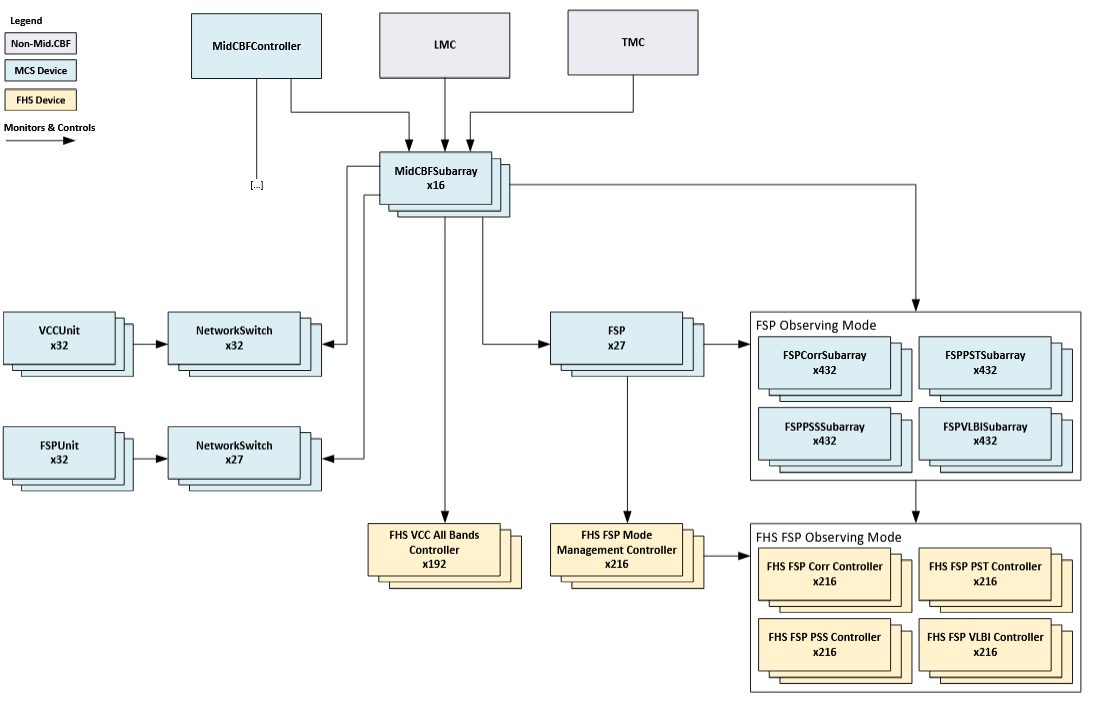
MCS Monitoring & Control - Subarray View
The CbfSubarray Tango device class implements control of Mid.CBF observing scan
operations, referred to herein as “scans”, which are the primary activity of the
Mid.CBF once operational state is initialized by the controller. MCS deploys 16
instances of these devices, which are the second external interface to the Mid.CBF
alongside the controller.
Scans: briefly, the Mid.CBF processes SKA Mid telescope dish output into meaningful output products for astronomical purposes, and scans are individual performances of this process by subarrays.
Subarrays: every instance of
CbfSubarrayrepresents a grouping of Mid.CBF resources called a “subarray,” an abstraction permitting the division of the full 192 dish array into independently operable sets, with each dish resource bound exclusively to a single subarray during resource assignment.
Scan observation configuration and operation is performed via its AssignResources,
ConfigureScan, Scan, EndScan, GoToIdle, ReleaseResources and
ReleaseAllResources commands, with an additional pathway for aborting in-progress
scan operation via its Abort, ObsReset and Restart commands.
Resource assignment
Assignment of dishes to subarrays is the first step in scan configuration, and is
accomplished via the AssignResources command. This assignment is exclusive;
dishes belonging to one subarray cannot belong to another subarray. Anywhere from
1 to 192 receptors can be assigned to any one subarray, and MCS supports up to 16
independent subarrays.
Specific dish resources from one subarray can be released for use by other subarrays
via the ReleaseResources command, or all of a subarray’s dishes can be released
via the ReleaseAllResources command.
Dishes and VCCs: in the Mid.CBF, the Very Coarse Channelizer, or VCC, ingests dish signal data. Each dish outputs exclusively to one VCC, therefore dish resources are often translated in MCS representation to their corresponding VCC, of which there are an equalling total amount of 192 available for subarray use.From here on out, dish resources will be referred to as VCCs, as the purposes of this document are for the elaboration of MCS concepts.
VCCs and FSPs: in the Mid.CBF, the VCC processes corresponding dish signal data into Frequency Slices (FS) which it outputs to the Frequency Slice Processor, or FSP, for further processing. Each one of the 27 FSPs receives data from every VCC, allowing subarrays to share an FSP if they require similar processing on the data output from different sets of VCCs. FSPs are continuously processing all VCC input streams, and subarrays merely enable the output of specific products pertaining to their assigned VCCs. FSP resource assignment and release is performed after VCC resource assignment with the
ConfigureScancommand.
Subarray VCC resources are represented by VCC All Bands Controller devices running on VCC Unit FPGA Host Servers (FHS), while FSP resources are represented by FSP observing mode devices in the MCS deployment - more detail is given on FHS, VCC and FSP architecture in subsequent sections.
Scan configuration
The ConfigureScan command is used to provide subarrays with key configuration
parameters that detail the specifics of a scan - most prominently which FSP resources
should be used by the subarray - and it may be called only after assignment of at
least one VCC.
FSPs are assigned to subarrays during ConfigureScan, and may be shared by any
number of subarrays so long as those subarrays are requesting processing for the
same observing mode (more details on this below). When an FSP is assigned to its
first subarray, that subarray will determine the observing mode; when an FSP is
released by all subarrays, it may be configured for a different observing mode.
The scan parameters are supplied to ConfigureScan in an ASCII-encoded JSON string.
This configuration is first validated for completeness; should all parameters pass
validation, the subarray device will then configure its subordinate VCC and FSP
resources with the relevant parameters.
Scanning
The Scan command is used to start a scan observation, and the EndScan command
to end the scan. Essentially, in Scan the subarray enables its assigned FSPs
to output their products, and in EndScan the subarray disables this output.
Any number of scans may be performed with the same configuration provided in ConfigureScan.
FPGA Host Server (FHS)
MCS FSP and VCC devices subordinate to controller and subarray are responsible for monitoring and control of devices running on the FPGA Host Servers, or FHS. Every FHS is a k8s node that will run Tango devices for controlling the signal-processing FPGAs in its Line-Replaceable Unit, or LRU. The low-level FHS devices are the level immediately below MCS in the Mid.CBF control software hierarchy, the means through which MCS performs all hardware monitoring and scan configuration.
The Mid.CBF hardware LRUs contain 1 FHS and 2 signal-processing FPGAs each, but the differences in VCC and FSP architecture require differing amounts of LRUs to perform the processing required in either part; the division is as follows:
1 VCC Unit is made up of 1 LRU, with 3 VCC resources per FPGA for a total of 6 VCC resources per VCC Unit.
1 FSP Unit is made up of 4 LRUs, with 8 FPGAs required to perform the processing of 1 FSP resource. As every FSP must receive output from all 192 VCCs, each FPGA in the FSP Unit will receive the output from 24 VCC resources.
Frequency Slice Processor (FSP)
In MCS, the 27 FSP resources are represented by 27 instances of the FspUnit
class subordinate to the controller, with every instance representing 8 FPGAs across
4 LRUs, each FPGA receiving the output of 24 VCC resources for a total of 192 VCC
input streams for every FSP. The FspUnit devices are each responsible for monitoring
8 FHS FPGA control devices, 8 FHS FSP Mode Management Controller devices, 8 FHS
FSP Correlation Controller devices, 8 FHS FSP Pulsar Timing Beamforming (PST) Controller
devices, 8 FHS FSP Pulsar Search Beamforming (PSS) Controller devices, 8 FHS FSP
Very-Long-Baseline Interferometry (VLBI) Controller devices, and 1 network switch
device, reporting health state and status for the entire unit to the controller.
The Fsp, FspCorrSubarray, FspPstSubarray, FspPssSubarray and FspVlbiSubarray
device instances are subordinate to the subarrays and are responsible for scan configuration,
monitoring and control of the FHS observing mode management and control devices.
Instances of
Fspmanage subarray membership of FSPs and perform observing mode management, switching FHS FSP configuration for different observing modes.There is one FSP observing mode subarray device for every unique pairing of subarray and FSP, for a total of 432 devices (16 subarrays * 27 FSPs) per observing mode; these perform FSP configuration for individual subarrays, allowing MCS to control FSPs with full subarray independence and observing state tracking for all scans performed on every FSP. FSPs may perform scan processing in four different observing modes (
ObsMode), each with a corresponding observing mode subarray device per unique subarray-FSP pairing.Correlation (
ObsMode.IMAGING):FspCorrSubarrayPulsar Timing Beamforming (
ObsMode.PULSAR_TIMING):FspPstSubarrayPulsar Search Beamforming (
ObsMode.PULSAR_SEARCH):FspPssSubarrayVLBI Beamforming (
ObsMode.VLBI):FspVlbiSubarray
HealthState - FSP
The FSPUnit device’s healthState attribute is an aggregate of its subordinate devices’ healthState attributes, which it monitors via subscription. These subordinate devices include:
1
Fspper FSP-UNIT4
FhsMonitorDeviceper FSP-UNIT(To Be Implemented) 1
NetworkSwitchper FSP-UNIT
FSP Unit is responsible with producing two other HealthState values, which are detailed below.
See HealthState Aggregation subsection in HealthState for more details on Health State Aggregation.
Health State |
Reason |
|---|---|
FAILED |
Hardware health state reports healthState.FAILED or the FSP device reports HealthState.FAILED or both report FAILED. |
DEGRADED |
Any 1 hardware health state or FSP device reports HealthState.DEGRADED or HealthState.UNKNOWN or Both hardware health state and FSP device report HealthState.DEGRADED |
UNKNOWN |
Both hardware health state and FSP device health state reports HealthState.UNKNOWN |
OK |
Hardware and FSP devices both report HealthState.OK |
FSP Unit Hardware Health State Aggregation
The FSPUnit device’s healthStateHardware represents the HealthState of the FSP-UNIT’s hardware components.
It is an aggregate of the HealthState values reported by the 4 FhsMonitorDevice devices, which monitor the health of the 4 Terabox LRUs in the FSP-UNIT, and the NetworkSwitch Tango device (to be implemented).
Below is a table that lists each Health State value used in FSP Unit Hardware Health State Aggregation.
Health State |
Reason |
|---|---|
FAILED |
At least 1 NetworkSwitch or FHS device reports HealthState.FAILED. |
DEGRADED |
Any 1 of NetworkSwitch, FHS device reports HealthState.UNKNOWN. Any 1 or both of NetworkSwitch, FHS device reports HealthState.DEGRADED. |
UNKNOWN |
All of NetworkSwitch, FHS device report HealthState.UNKNOWN. |
OK |
Network Switch and FHS device both report HealthState.OK |
FSP Unit Signal Processing Health State
The FSPUnit device also implements the following HealthState-related attributes to represent health of the signal processing components:
healthStateFsp
HealthState of the FSP resource that is available to the FSP Unit.
resourceStatus
See FSP Unit ResourceStatus Attribute section
FSP Unit ResourceStatus Attribute
resourceStatus reads and gather status from the FSP available to
the FSP Unit. The status are then compiled into a ResourceStatus report.
resourceStatus contains the following information for the available FSP:
Which Subarrays are using the
FSPObsMode of the
FSPHealthState of the
FSPAdminMode status of the
FSPFSP Unit ID that the
FSPbelongs to
See the FSP Detail Status section in the latest Telescope Model ResourceStatus schema for more detail.
Very-Coarse Channelizer (VCC)
In MCS, the 192 VCC resources are represented by 32 instances of the VccUnit
class subordinate to the controller, each monitoring a hardware VCC Unit LRU comprising
2 FPGAs with 3 VCC resources - thus, 6 VCC resources per VCC Unit. The VccUnit
instances are each responsible for monitoring 1 FHS FPGA control device, 6 FHS VCC
All Bands Controller devices and 1 network switch device, reporting health state
and status for the entire unit to the controller.
HealthState - VCC
MCS VCC Unit’s healthState attribute is an aggregate of its subordinate devices’ healthState attributes, which it monitors via subscription. These subordinate devices include:
6
VCCAllBandsControllerfor the 6 VCC resources per VCC-UNIT1
FhsMonitorDeviceper VCC-UNIT(To Be Implemented) 1
NetworkSwitchper VCC-UNIT
VCC Unit is responsible with producing two other HealthState values, which are detailed below.
See HealthState Aggregation subsection in HealthState for more details on Health State Aggregation.
Health State |
Reason |
|---|---|
FAILED |
VCCUnit Hardware healthstate reports HealthState.FAILED, or all VCCAllBandsController devices report HealthState.FAILED |
DEGRADED |
Hardware healthstate reports HealthState.DEGRADED or UNKNOWN, or any 1 VCCAllBandsController device reports HealthState.FAILED or Healthstate.UNKNOWN |
UNKNOWN |
Hardware healthstate and VCCAllBandsController devices report HealthState.UNKNOWN |
OK |
Hardware healthstate and VCCAllBandsController devices report HealthState.OK |
VCC Unit Hardware Health State Aggregation
The VCCUnit device’s healthStateHardware represents the HealthState of the VCC-UNIT’s hardware components.
It is an aggregate of the HealthState values reported by the FhsMonitorDevice device, which monitors the health of the Terabox LRU in the VCC-UNIT, and the NetworkSwitch Tango device (to be implemented).
Below is a table that lists the reasoning for each HealthState value for VCC Unit Hardware Health State Aggregation.
Health State |
Reason |
|---|---|
FAILED |
NetworkSwitch or Terabox Monitor device reports HealthState.FAILED |
DEGRADED |
Terabox Monitor reports FAILED, UNKNOWN or DEGRADED and Switch reports OK. Terabox Monitor reports FAILED, UNKNOWN or DEGRADED and Switch reports DEGRADED. |
UNKNOWN |
Both NetworkSwitch and Terabox Monitor devices report HealthState.UNKNOWN |
OK |
Both NetworkSwitch and Terabox Monitor devices report HealthState.OK |
VCC Unit Signal Processing Health State
The VCCUnit device also implements the following HealthState-related attributes to represent health of the signal processing components:
healthStateVccs
JSON string which contains a list of VCC and their aggregated signal processing and VccUnit hardware healthstate.
resourceStatus
See VCC Unit ResourceStatus Attribute section
Health State |
Reason |
|---|---|
FAILED |
Either The VCC All Bands Controller for the VCC or the VCCUnit Hardware HealthState is HealthState.FAILED, DEGRADED, or UNKNOWN |
DEGRADED |
Not Used – no known scenarios where only part of the VCC functionality is available |
UNKNOWN |
VCC All Bands Controller device for the VCC and the VCC Hardware HealthState isHealthState.UNKNOWN |
OK |
FHS VCC All Bands Controller for the VCC or the VCC Hardware HealthState is All NetworkSwitch, TeraBox and VCCAllBandsController devices report HealthState.OK |
VCC Unit ResourceStatus Attribute
resourceStatus reads and gather status from all the VCC available to
the VCC Unit. The status are then compiled into a ResourceStatus report.
resourceStatus contains the following information for each of the available
VCC:
Which Subarray is using the
VCCHealthState of the
VCCAdminMode status of the
VCCVCC Unit ID that the
VCCbelongs to
See the VCC Detail Status section in the latest Telescope Model ResourceStatus schema for more detail.
Mid.CBF Base Class Inheritance
Mid.CBF devices extend the ska-tango-base base device class SkaBaseDevice
with its own pair of base classes: CbfDevice and CbfObsDevice.
Likewise, Mid.CBF’s component management classes CbfComponentManager and CbfObsComponentManager
extend TaskExecutorComponentManager (itself an extension of BaseComponentManager)
to enable asynchronous command execution via Long Running Commands (LRCs).
This is done to override the ska-tango-base implementation as needed.
For example, CbfObsDevice initializes a slightly reduced observing state model
that omits the EMPTY and RESOURCING states since they are not required by
MCS observing devices, with the exception of CbfSubarray which implements the
full ObsState model.
State Models
There exist a handful of state models implemented in the SKA control model that are inherited by MCS devices. Some notes regarding the most important of these, along with the states used by MCS and related terminology, are listed here:
AdminMode
When a device’s adminMode attribute is set to ONLINE it triggers the component manager’s
start_communicatingmethod, establishing monitoring and control over the underlying component; when set to OFFLINE, it triggersstop_communicating, disengaging component monitoring and control.When the device is “online” (i.e. communications are established with the component,
AdminMode.ONLINE), its operating state (OpState) is controlled via power state updates (e.g. ON, OFF).Note that while these OpState transitions generally occur within On/Off commands, some devices do not implement On/Off commands and instead use
start_communicatingandstop_communicatingto toggle their OpState. This is done in devices where there is no functional difference between establishing communication with the device’s component, and “powering on” the device.
When the device is “offline” (i.e. communications with the component are disabled,
AdminMode.OFFLINE), its operating state is DISABLE.
OpState
An extension of Tango’s DevState. Changes in both power state and communication status drive updates to the OpState for a given device. For more details see _communication_state_changed and _component_state_changed methods in SKABaseDevice.
States used in MCS: ON, OFF, DISABLE.
Typically referred to when “powering on” or “powering off” a device, via the On/Off commands.
Reduced OpState model used in Mid.CBF devices:
ObsState
Used by observing devices to denote what stage of an observation/scan is in progress. This state is driven by observing commands.
Normal scan operation states: EMPTY, RESOURCING, IDLE, CONFIGURING, READY, SCANNING.
Abort pathway states: ABORTING, ABORTED, RESETTING, RESTARTING.
Note: resources such as VCC and FSP do not implement EMPTY, RESOURCING and RESTARTING states, nor resourcing commands, as they do not require resource allocation prior to scan configuration.
Reduced ObsState model used in basic Mid.CBF observing devices
![@startuml
skinparam linetype ortho
IDLE: The device is unconfigured
CONFIGURING: The device is performing a configuring operation
READY: The device is configured
SCANNING: The device is scanning
ABORTING: The device is aborting
ABORTED: The device has aborted
RESETTING: The device is resetting to IDLE\nfrom FAULT or ABORTED state
FAULT: The device has faulted
INIT -down-> IDLE
IDLE -down-> CONFIGURING
IDLE -left-> ABORTING
CONFIGURING -up-> IDLE
CONFIGURING -down-> READY
CONFIGURING -left-> ABORTING
READY -up-> CONFIGURING
READY -up-> IDLE
READY -down-> SCANNING
READY -left-> ABORTING
SCANNING -up-> READY
SCANNING -left-> ABORTING
ABORTING -up-> ABORTED
ABORTED -up-> RESETTING
ABORTED -[hidden]left-> FAULT
RESETTING -down-> ABORTING
RESETTING -right-> IDLE
[*] -up-> FAULT
FAULT -up-> RESETTING
@enduml](../../_images/plantuml-3eb58813ec7481dec58dc038ebef36970b26bd9e.png)
Full ObsState model used in Mid.CBF subarray devices
![@startuml
skinparam linetype ortho
EMPTY: The subarray has no resources
RESOURCING: The subarray is performing a resourcing operation
IDLE: The subarray is unconfigured
CONFIGURING: The subarray is performing a configuring operation
READY: The subarray is configured
SCANNING: The subarray is scanning
ABORTING: The subarray is aborting
ABORTED: The subarray has aborted
RESETTING: The subarray is resetting to IDLE\nfrom FAULT or ABORTED state
RESTARTING: The subarray is restarting to EMPTY\nfrom FAULT or ABORTED state
FAULT: The subarray has faulted
INIT -down-> EMPTY
EMPTY -down-> RESOURCING
EMPTY -left-> RESTARTING
RESOURCING -up-> EMPTY
RESOURCING -down-> IDLE
IDLE -up-> RESOURCING
IDLE -down-> CONFIGURING
IDLE -left-> ABORTING
CONFIGURING -up-> IDLE
CONFIGURING -down-> READY
CONFIGURING -left-> ABORTING
READY -up-> CONFIGURING
READY -up-> IDLE
READY -down-> SCANNING
READY -left-> ABORTING
SCANNING -up-> READY
SCANNING -left-> ABORTING
ABORTING -up-> ABORTED
ABORTED -up-> RESETTING
ABORTED -up-> RESTARTING
RESETTING -down-> ABORTING
RESETTING -right-> IDLE
RESTARTING -right-> EMPTY
[*] -up-> FAULT
FAULT -up-> RESETTING
FAULT -up-> RESTARTING
@enduml](../../_images/plantuml-f260b09c41e8c2196837018ae8a4949039297438.png)
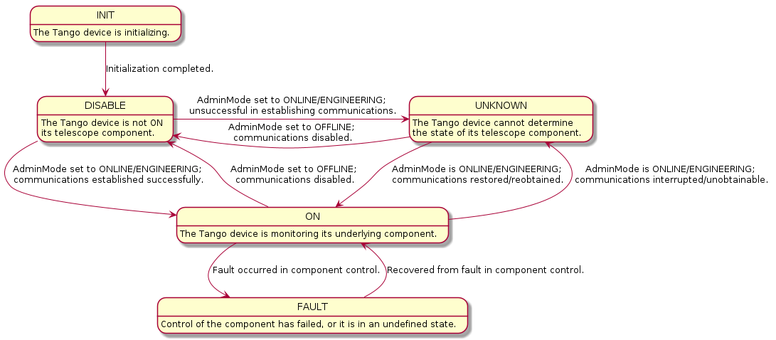
HealthState
Used to assess the ability of a device to perform its function. Reading a device’s
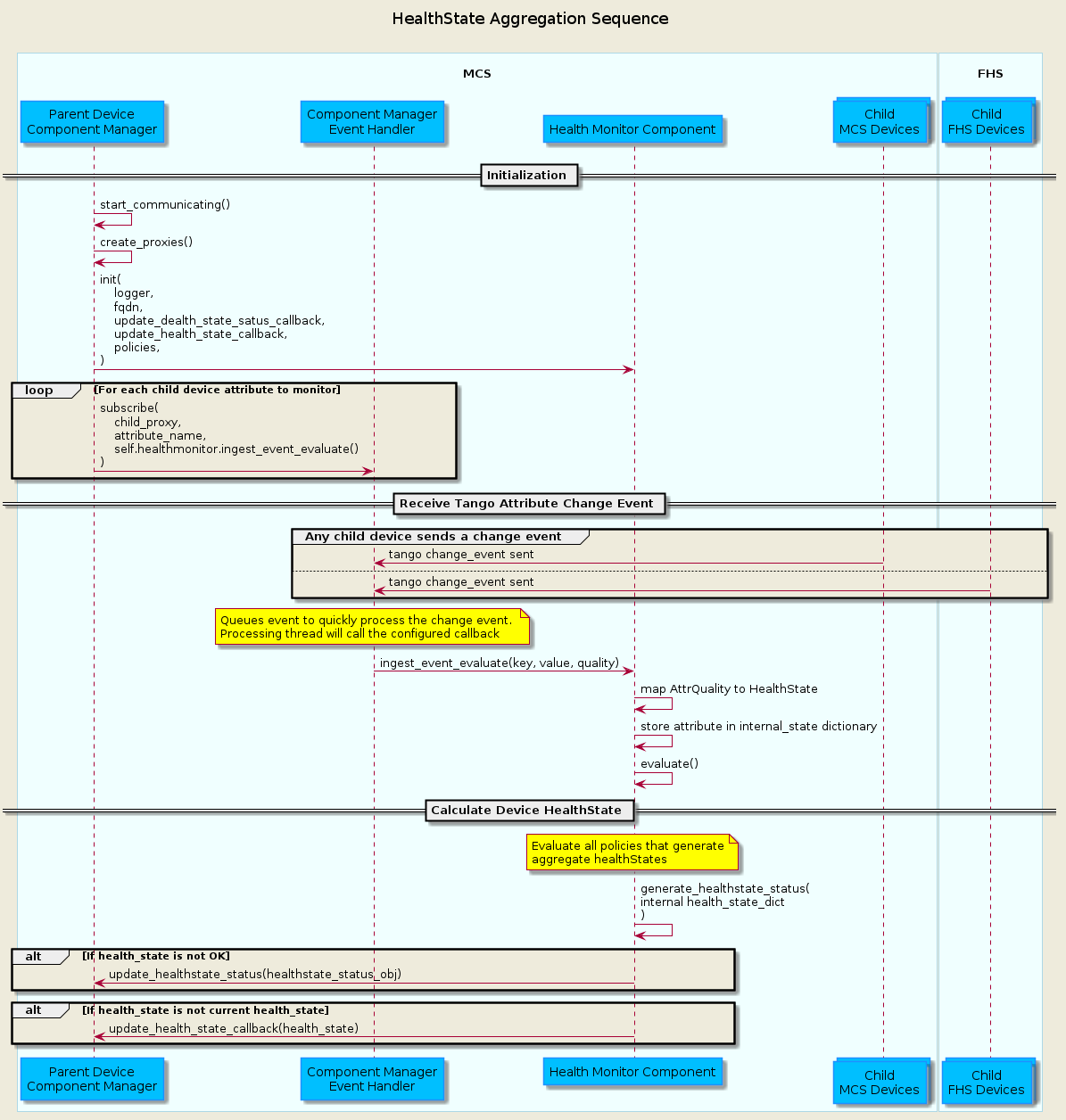
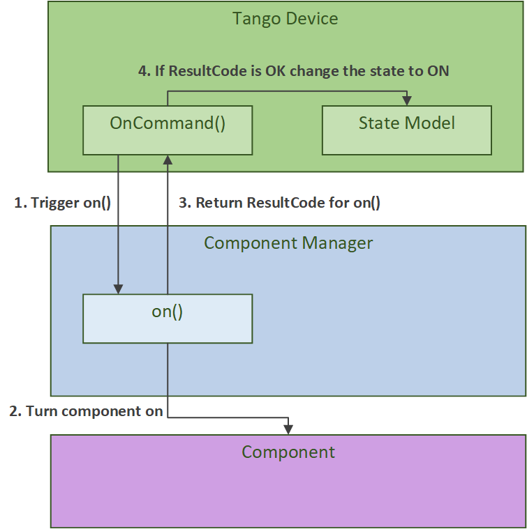
healthStateattribute performs specific checks for different devices, and is generally used by higher-level “parent” devices to summarize (“aggregate” or “roll-up”) the health the lower-level “child” devices they control. The devices that use the healthState attribute each have descriptions in previous sections detailing their particular implementation.Aggregation of child device
healthStateinto the parenthealthStatewill be handled using the HealthMonitorComponent. An MCS Tango devices’s ComponentManager will initialize the Health Monitor Component with the policies that influence how the child devices aggregate into the parenthealthState, then use its EventHandler to subscribe the HealthMonitorComponent’s ingest functions to child attributes to monitor for Tango change events. An example of this interaction is shown in the diagram below.
Devices and Component Managers
In the Mid.CBF MCS, each Tango device comprises a device class and a component manager class.
The device class provides a Tango interface, initializing properties, attributes, commands
and any related state machines. Every device further instantiates its own component manager,
which is used to perform the monitoring and control of the underlying component.
The component manager communicates information back up to the device via callbacks
and attribute signals;
in particular it triggers state transitions for AdminMode, HealthState,
OpState and ObsState.
More details about the role of component managers can be found in the SKA Tango Base Documentation. An example of this Tango device and component manager interaction is shown in the diagram below.
Asynchronous Event-Driven Control Structure
MCS version 1.0.0 introduces the concept of an event-driven system, which solves some timing challenges and provides additional benefits, at the expense of increased complexity.
Long-Running Commands (LRC)
Some operations in the CBF take time and there’s no getting around it. Before the event-driven approach was in place, a workaround used in MCS was to have clients temporarily increase a component’s timeout from the default 3 seconds before issuing calls, then revert this change after completion. Since this is clearly a hacky solution, an alternative was needed.
The upgrade of MCS to version 1.0.0 of ska-tango-base introduced the LRC Protocol.
An LRC’s immediate result_code indicates only whether the command was added to the TaskExecutor’s queue,
or was rejected, for example, due to the TaskExecutor’s queue being full. Once queued, commands are
executed within a separate “task-executor thread” running in parallel to the main control thread.
The actual results of LRCs come from published longRunningCommandResult attribute change events.
The value of this attribute is a tuple of (command_id, result_code_message), a slightly odd format
since result_code_message is a list(int, str) cast into a string, containing the result_code integer
and message string; for example: command_id, result_code_message =
('1725379432.518609_238583733127885_ReleaseAllResources', '[0, "ReleaseAllResources completed OK"]').
In devices, all commands are implemented with an @command-decorated method that initiates the command when called,
and an “execution” or “task” method in the component manager; this where the command’s logic lives.
Additionally, the device implements an is_<COMMAND>_allowed() method as a condition to guard the
component manager call in case a command is called from an invalid state, etc.
Another implication of parallelism in MCS is that multiple commands can be queued
without regard for their results, or even for how long they take to run (at least until their results are needed),
which solves the hacky update-command-timeouts workaround. Instead, once queued, LRCs rely on change events to
communicate their progress. The relevant devices’ longRunningCommandResult attributes are subscribed to during
component manager initialization, and a callback mechanism detects these events and keeps track of who is waiting
on what results, which opens the door for even further complexity: when a ‘parent’ LRC calls a ‘child’ command
on one of its components that is also an LRC - a nested LRC call.
To manage this confusing use case, command execution is blocked from getting too far ahead of the components’ LRC results by a) keeping track of how many LRCs remain in progress for a given client, and b) enforcing a final (much longer) timeout for LRCs, after which time the client must give up and call the original command a failure.
This is implemented and documented in further detail in the CbfComponentManager.issue_group_command method.
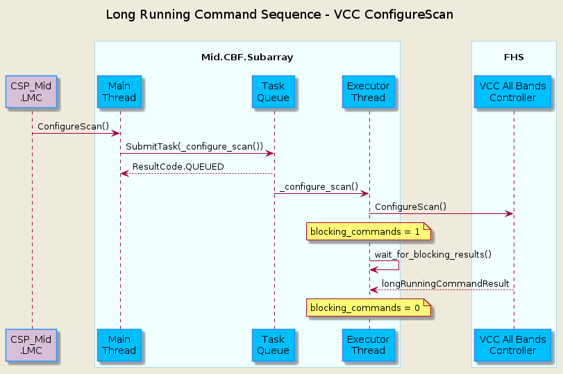
The following sequence diagram illustrates the LRC mechanism. Note that for simplicity, only a subset of
the CbfSubarray ConfigureScan() execution is shown, up to the end of the calls to the Vcc device.
This was done because including the FSP calls, etc. would over-complicate the diagram, and its purpose is
to illustrate the LRC sequence, not the ConfigureScan sequence.
In addition to protecting the blocking_commands set, locks also protect state transitions, as well as certain important attribute accesses,
such as healthState and CbfSubarray.lastDelayModel. Some of these locks are not currently necessary, but as event-driven functionality
continues to be added to MCS, new change event callbacks may opt to update these resources, so locks were proactively added.
Testing Approaches
For more detailed documentation on the testing infrastructure leveraged by MCS see ska-tango-testing
Test Naming Convention
Every test module must contain both a
conftest.pyfile containing test fixture setup and a<device_name>_test.pycontaining a test class with test cases defined as class methods.Test method names must begin with
test_, followed by the primary Tango attribute or command to be tested (e.g.adminModeorConfigureScan) and any additional modifier to describe device states or preconditions under test; some examples:test_adminMode: simply test reading deviceadminModeattributetest_adminMode_ONLINE: test setting deviceadminModeattribute toAdminMode.ONLINEtest_ConfigureScan: test deviceConfigureScancommand for success under happy-path conditions.test_ConfigureScan_invalid: test deviceConfigureScancommand with invalid input argument to try and induce command failure.test_ConfigureScan_EMPTY: test deviceConfigureScancommand fromObsState.EMPTYstate, which is not allowed, to try and induce command failure.test_AssignResources_ReleaseResources_unassigned: test both the deviceAssignResourcesandReleaseResourcescommands, with input arguments for resources that are not assigned to the device to try and induceReleaseResourcesfailure.
TangoEventTracer
In order to monitor and validate all device events during testing,
a TangoEventTracer is created during test suite initialization.
The event tracer is provided device attributes to monitor for Tango change events
during test runtime, and is then used inside test cases to assert event occurrences,
using assertpy predicate syntax.
Expected events are typically supplied as tuples containing 4 items to the assert_events
method provided in the ska_mid_cbf_mcs.testing.assertions module, with special
cases for custom matchers using the 3 item format; tuples should be formatted thusly:
4 items: (attribute_name, expected_value, previous_value, number_of_events)
3 items using custom matcher: (attribute_name, custom_matcher, number_of_events)
Test setup for both integration/k8s and unit tests requires a TangoEventTracer
to be instantiated that subscribes to all events that must be validated during test
execution. Some examples are provided below;
@pytest.fixture(name="event_tracer", autouse=True)
def tango_event_tracer(
    controller: DeviceProxy,
) -> Generator[TangoEventTracer, None, None]:
    """Fixture that returns a TangoEventTracer for the controller device."""

    # Set up TangoEventTracer to properly report enum attributes.
    # NOTE: event_enum_mapping does not work with DevState
    tracer = TangoEventTracer(
        event_enum_mapping={
            "adminMode": AdminMode,
            "obsMode": ObsMode,
        }
    )

    # Subscribe to controller events.
    tracer.subscribe_event(controller, "adminMode")
    tracer.subscribe_event(controller, "state")

    # Yield tracer and clean up events when it is no longer in use.
    yield tracer
    tracer.unsubscribe_all()
    tracer.clear_events()
def test_adminMode_ONLINE(
    controller: DeviceProxy,
    event_tracer: TangoEventTracer,
    event_timeout: int,
) -> None:
    """Test the initial states and verify the component manager can start communicating."""

    # Trigger start_communicating by setting the AdminMode to ONLINE.
    controller.adminMode = AdminMode.ONLINE

    # Validate controller events were received by the event tracer.
    expected_events = [
        ("adminMode", AdminMode.ONLINE, AdminMode.OFFLINE, 1),
        ("state", DevState.OFF, DevState.DISABLE, 1),
    ]
    proxy_list = [controller]
    assert_events(expected_events, proxy_list, event_tracer, event_timeout)
Test Parametrization
PyTest parametrization is heavily relied-upon to structure test execution in both integration/k8s and unit test modules, with the most complex parametrization evident in the k8s test suites for controller and subarray.
Essentially, parametrization is done in 2 layers:
Fixture input parameters: one key fixture, typically named
<device_name>_params(e.g.controller_paramsorsubarray_params) is itself parametrized using the@pytest.fixturedecorator with theparamsargument, which is supplied with key parameters to determine the scope of the testing to be performed, such as a list of VCC and FSP resources to use, or the frequency band to configure for scan testing. This fixture takes in these simple, user-defined parameters and transforms them into the full data sets that are to be ingested by the device(s) under test.Fixture output parameters: Every test method in the module is parametrized with this key fixture, i.e. every method takes in
<device_name>_paramsas a keyword input argument, and will pull relevant data during test execution from the set generated by the fixture.
This 2-layer parametrization means that users define simple data sets that are appended to the list of fixture input parameters which will cause every test in the module to run for each set of fixture output parameters. Every module then can be defined to test device behaviour regardless of input argumentation specifics, and every pass of the modules will validate device behaviour given different preconditions.
Test parameter generation tools are found in the ska_mid_cbf_mcs.testing.param_gen
module of the MCS Python source code.
Integration/k8s Testing
Test dependency
In the test modules defined in the tests/k8s/ directory, tests are of a functional
nature, validating system-wide behaviour driven through the primary external interfaces
of the controller and the subarray device; consequently, there are only 3 sets of
tests here: controller, single-subarray and multi-subarray test modules.
In each of these test sets, the system is driven solely through the relevant external interface, but the entire system is deployed via Kubernetes, or k8s. Since the full MCS is alive and thus performing complex, interdependent operations and communications between its constituent devices, the structure of these tests must be carefully considered: every test will influence the starting conditions of the test immediately succeeding it, same as for every test module.
Each one of the 3 test modules (controller, single-subarray and multi-subarray)
should return the entire system to its nominal initialized state. This basically
means that every device should be returned to OpState.DISABLE, AdminMode.OFFLINE,
with observing devices in ObsState.IDLE and subarray devices in ObsState.EMPTY;
however, there are a multitude of other states and attributes to be carefully
considered and returned to nominal startup values. One key test case, test_reset,
is provided at the end of each test module for performing any activities and validation
to ensure all devices are reset for the next test module.
FHS simulators
Since MCS monitors and controls FHS devices, which are not tested at the level of
MCS k8s tests, FHS device simulators are deployed alongside MCS devices to simulate
a responsive FHS system. Detailed information on simulator behaviour can be found in
the documentation for the ska_mid_cbf_fhs_common.simulation module, but the
pertinent facts are summarized below:
FHS simulator devices use the same Tango device interface as the genuine devices, but return by default happy-path responses to all attribute and command requests.
If non-happy-path responses are required during MCS tests, these simulated responses can be overriden using the devices’
simOverridesattribute. This attribute takes in a JSON-formatted string containing attribute and command behavioural overrides, which are queued - this means that multiple overrides can be supplied at once in the beginning of a test, and the simulators will return these responses on a FIFO basis. This is particularly useful for concurrent multi-subarray tests, wherein multiple MCS subarrays may be communicating with the same FHS resource simulators at roughly the same time in order to validate subarray independence; a given simulator that is expected to reply to 2 different subarrays during a test can have 2 different responses queued throughsimOverridesat the top of the test case, and will return the 2 different responses to each of the 2 subarrays on a FIFO basis depending on the minute ordering of the near-simultaneous requests.
Unit Testing Harness
In order to properly unit test individual Tango device modules in the tests/unit/
directory we make use of ska-tango-testing test contexts, in particular the
ThreadedTestTangoContextManager, which is based on Tango’s MultiDeviceTestContext.
Since all MCS devices communicate with entities external to themselves (mainly
other Tango devices), the test context is used to run an individual device without
a Tango database, and pytest fixtures are set up to build mock objects as targets
for device communications in place of live targets. A particularly important case here
is of Tango device mocks, generated with use of the MockDeviceBuilder class,
and swapped in for actual Tango DeviceProxy objects when the test context is entered;
this is why the ska_tango_testing.context.DeviceProxy wrapper for DeviceProxy
is used in the source code.
Improvements to Control Flow
The upgrade to ska-tango-base v1.0.0 provided an opportunity to reduce technical debt and
consolidate the MCS code base in general.
The biggest change is the removal of On/Off commands from devices that do not directly control hardware power,
since these devices do not need to distinguish between having communication established and being turned on.
Rather than explicitly issue On/Off commands to update the OpState model in these devices, the PowerState enum is
instead set as the end of start_communicating() and stop_communicating() methods, which run after setting
the AdminMode attribute to AdminMode.ONLINE and AdminMode.OFFLINE, respectively. In the rest of
the MCS devices (the ones that do implement On and Off commands), these methods set the
CommunicationStatus attribute to CommunicationStatus.ESTABLISHED and CommunicationStatus.DISABLED,
respectively; they also set AdminMode.UNKNOWN during stop_communicating() to move the
OpState model, since setting CommunicationStatus.NOT_ESTABLISHED has no action.