ADC Test
Purpose
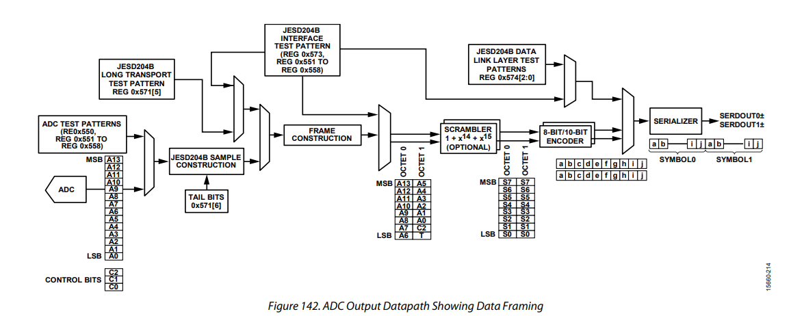
This test verifies the capture of simulated raw voltage data by generating ADC data patterns. As these data patterns are generated by the AD9695 ADCs, this test also verifies the operation of the JESD204B link between the ADCs and the FPGAs. The position of the ADC data pattern insertion can be seen in the below diagram of the ADC ouput datapath, “ADC Test Patterns”:
To capture and verify the propagating data pattern from the FPGAs, the software requests the LMC data type “raw data” from the TPM, and captures this using the DAQ receiver.
NOTE: This test operates on all TPMs in a station individually. For data acquisition to function correctly, the network interfaces on the TPM must be working, as well as the link to the LMC destination. The LMC destination must be configured to route traffic to the server running the tests. For all tests the simplest option is for the CSP and LMC destinations to be the same network interface, routing all traffic to the server running the tests.
Currently this test supports automated verification of the following ADC Test Modes:
fixed: A repeating pattern of four user provided values.
ramp: A linear ramp pattern increasing from 0x000 to 0x3FFF then repeating.
Additionally the ADC and TPM API support these ADC Test Modes which do not yet have automated verification in this test:
midscale: A constant output of the ADC midscale value.
full-scale-positive: A constant output of the ADC positive maximum value.
full-scale-negative: A constant output of the ADC negative maximum value.
checkerboard: A repeating pattern of alternating 1’s and 0’s. Words alternate between 0x2AAA and 0x1555.
pn-long: A PN23 (Pseudo-Random Noise) sequence.
pn-short: A PN9 (Pseudo-Random Noise) sequence.
one-zero-alternate: A repeating pattern of alternating 1’s and 0’s. Words alternate between 0x0000 and 0x3FFF.
For more details see the Analog Devices AD9695 Data Sheet
Methodology
DAQ receiver is configured and initialised with the required UDP port and network interface.
A ramp pattern is configured and enabled on the TPM at the output of the ADCs
An LMC snapshot of raw voltage data is requested from the TPM
The captured data is received over 40GbE and compared to the expected pattern
This is repeated for a fixed data pattern.
Typical issues
Some typical issues and how they present are shown below:
Presentation: No data is received. Test halts indefinitely waiting for SPEAD packets.
Issue: Network configuration issue. Check the MTU is set to 9000 on every switch, port, VLAN or NIC in the chain.