Names used within Low.CBF
P4 network switches (P4s) and Alveo cards are key hardware elements of Low.CBF, together with IO connections to SPS, PST, PSS, and SDP. Software identifies the items it manages by means of a unique name. Names include:
Switches: “p4_01”, “p4_02” (or we might use a serial number)
Switch ports: “10/0”, “3/1”, ie port number/lane
Alveo cards: “alveo_000”, “alveo_001” (or a serial number)
PST servers: “pst_01” (or IP address). Each server will be associated with one switch port.
PSS servers: “pss_01” (or IP address). Each PSS server will be associated with one switch port.
SDP servers: “vis_01” (or IP address). Each SDP server will be associated with one switch port.
Stations: “stn_001” (or IP address). Each station will be associated with one switch port. All of a station’s substations, if any, will connect at the same switch port.
Description of Low.CBF Structure
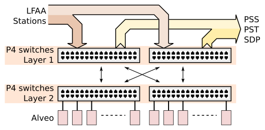
Low.CBF will have two network switch layers, except in the first two (smallest) array releases with only a single switch. Stations and I/O to SDP, PSS and PST servers connect to the first layer of switches. Alveo cards connect to the second layer of switches. Each first layer switch is connected by optical links to every second layer switch, allowing data from any station to reach any Alveo for processing, and data products from any Alveo to be sent to any I/O link.
Software learns the structure of the connections between Alveo cards, P4 switches and IO links by means of a list of interconnections provided to it. The list is provided in the ‘allocator.yaml’ file used by the Helm chart to deploy Low.CBF into K8s. It contains a one-line entry for each network link that is physically present in Low.CBF hardware. By using different lists for different sites, local hardware can be adapted to.
- There are three general classes of connections:
- switch-to-switch, representing a (bi-directional) link between two switches eg:
‘switch=p4_01 port=29/0 speed=100 switch2=p4_03 port2=3/0’
- switch-to-alveo, indicating which switch and which switch port an Alveo FPGA card connects to, eg:
‘switch=p4_01 port=48/0 speed=100 alveo=XFL1ZIN0F4RO’
- switch-to-I/O link for connecting with stations, SDP, PST or PSS servers, eg:
‘switch=p4_01 port=29/0 speed=100 link=stn_003’
‘switch=p4_01 port=28/0 speed=100 link=sdp_001’
‘switch=p4_01 port=31/0 speed=25 link=pst_001’
‘switch=p4_01 port=30/0 speed=25 link=pss_001’
The information in the Helm chart must be consistent with physical hardware otherwise routing information calculated for the switches by the allocator will be incorrect and Low.CBF will not function as intended.
Frequency Slice Processors
Deprecated. The “fsps” section of subarray configure commands is ignored in 0.11.4 and scheduled for removal. FPGA resources are now automatically assigned to subarrays on configuration.
Low.CBF Subarray Resources
For Low.CBF, the Subarray.AssignResources command is an empty JSON string, and simply moves the obsstate state machine between EMPTY and IDLE states. The AssignResources command exists to allow SDP and PST to be configured to receive data from Low.CBF and generate a list of destinations that outputs should be sent to. The destinations are subsequently provided as part of the Low.CBF ConfigureScan command.
The Subarray.ConfigureScan command provides almost all the information that Low.CBF requires to determine which of the shared compute resources will be used to calculate the output products that a subarray requires. It specifies:
a list of stations or sub-station from which the subarray expects to receive data from SPS
a list of the station beams and beam frequencies each SPS station will send to Low.CBF
The output products desired, and the destination for the products:
Visibilities
PST beams
PSS beams
Allocator
The allocator is the central coordinator for sharing of Low.CBF resources among subarrays. To perform this function, it maintains internal variables representing the entire current state of Low.CBF and updates the state as a result of successive subarray requests for resources.
- The state is published via Tango attributes:
internal_alveo
internal_subarray
stats_alveo
The internal_alveo attribute publishes a JSON string encoding a dictionary that describes the frequencies, channels, and subarrays that each Alveo is to process, and the type of processing (correlation, PST, etc).
The internal_subarray attribute also publishes a JSON string encoding a dictionary. The entries describe every subarray that is currently active in Low.CBF.
- The description contains information about:
- inputs for each subarray:
stations and sub-stations contributing data to the subarray
station-beams that belong to the subarray
a list of frequency_ids for each station-beam
- outputs that the subarray generates
Visibilities, and their SDP destinations
PST beams and their PST server destinations
PSS beams and their PSS server destinations
The stats_alveo attribute publishes a JSON string that describes each alveo, its usage by subarrays, and any unused capacities that it may have
The allocator also publishes attributes containing routing information for P4 switches. Routes are calculated internally from the Alveo and subarray information and so do not represent additional state the allocator maintains.
Allocation Process
When the Allocator receives a request for a new subarray it has to determine whether the request can be satisfied with the resources it has available, and how the computation requested should be partitioned between the available Alveos. Available resources fluctuate because subarrays share Low.CBF and resources used by one subarray detract from resources remaining for other subarrays.
Requests are broken down into their component parts - visibilities or beams - and for each frequency of each station-beam, reservations are made in the Alveos that are running the requisite firmware. If the process is successful the reservation is confirmed, and the new state is published via Allocator attributes. On the other hand, if the process runs out of Alveo cards for any of the request components before completing, the reservation is cancelled and the state of the Allocator does not change. Subarrays are notified whether their resourcing requests succeed.
The process of determining whether a particular Alveo can accommodate workload of a new subarray is different for each different FPGA personality. A separate source code file is used for each for each different personality. Each file has its own suite of test cases to ensure it produces expected failures or successes with several corner-case requests.