The Installed Pipelines
YANDASoft
The YANDASoft pipelines are presented in a number of ways. The simplest is a NextFlow pipeline. NextFlow is a simple computational pipeline described here <https://www.nextflow.io>
An individual pipeline is presented for each test. And a common configuration is presented for all tests.
The Functional Test
This test is a simple imaging test it contains a 1Jy point source slightly off the image phase centre. The simulation was generated with the ASKAP simulation tools and is just included here as a demonstration of a simple pipeline.
The Input Data
The measurement set for it is included in ./data/functest.ms it is a small, 8 channel ASKAP simulation.
The Configuration File
This deployment of YANDASoft is controlled by a configuration file. All of the aspects of the processing are controlled by this file. This particular implementation is going to image, deconvolve and restore the input simulation.
The configuration file for this processing is included in ./configs/functest.in:
Cimager.dataset                                 = [functest.ms]
Cimager.imagetype                               = casa
Cimager.memorybuffers                           = true
Cimager.barycentre                              = false
Cimager.nchanpercore                            = 8
Cimager.combinechannels                         = true
Cimager.Images.Names                            = [image.cont]
Cimager.Images.shape                            = [128,128]
Cimager.Images.cellsize                         = [5arcsec, 5arcsec]
Cimager.visweights                              = MFS
Cimager.visweights.MFS.reffreq                  = 1.1e+09
Cimager.Images.image.cont.frequency             = [1.1e+09,1.1e+09]
Cimager.Images.image.cont.nterms                = 2
Cimager.Images.image.cont.nchan                 = 1
Cimager.nworkergroups                           = 3
Cimager.sensitivityimage                        = true

Cimager.gridder                                 = WProject
Cimager.gridder.WProject.wmax                   = 20000
Cimager.gridder.WProject.nwplanes               = 51
Cimager.gridder.WProject.oversample             = 8
Cimager.gridder.WProject.maxsupport             = 1024
Cimager.gridder.WProject.cutoff                 = 0.001
Cimager.gridder.WProject.variablesupport        = true
Cimager.gridder.WProject.offsetsupport          = true

Cimager.ncycles                                 = 6
Cimager.Images.writeAtMajorCycle                = true

# Use a multiscale Clean solver
Cimager.solver                                  = Clean
Cimager.solver.Clean.solutiontype               = MAXCHISQ
Cimager.solver.Clean.decoupled                              = True
Cimager.solver.Clean.algorithm                  = BasisfunctionMFS
Cimager.solver.Clean.scales                     = [0]
Cimager.solver.Clean.niter                      = 10000
Cimager.solver.Clean.gain                       = 0.3
Cimager.solver.Clean.logevery                   = 1000
Cimager.threshold.minorcycle                    = [40%,2mJy,0.18mJy]
Cimager.threshold.majorcycle                    = 10mJy

Cimager.solver.Clean.verbose                    = false

Cimager.preconditioner.preservecf               = true
Cimager.preconditioner.Names                    = [Wiener]
Cimager.preconditioner.Wiener.robustness        = 2.0

Cimager.restore                                 = true
Cimager.restore.beam                            = fit
I will not go through all the configuration options here they are described at <https://yandasoft.readthedocs.io/en/latest/calim/imager.html>.
The important things to note are:
Cimager.visweights = MFS
Which denotes that we are processing using Multi Frequency Synthesis. Which in this case is a representation of the bhaviour of the flux as a fuctional of frequency that is characterised by a Taylor decomposition:
Cimager.Images.image.cont.nterms = 2
Our Taylor decomposition will output 2 Taylor-frequency terms. It should be noted that my input simulation has no frequency dependence - so the terms higher than 0 will be empty.
The Taylor term decomposition requires that the same input data be reweighted for each term. This is massively parallel by frequency until deconvolution so is performed in parallel by:
Cimager.nworkergroups = 3
3 Worker groups. All the gridding and imaging will be distributed into 3 groups. Which means the jobs is now configured to run as a 4 (four) rank MPI job.
The gridding is pure W-projection as the image has only a very simple source close to the phase centre the imaging is very robust to this. But for completeness the parameters are included.
Other points to note are the solver is a basis function solver - but only a 0-basis is being used. A Wiener filter is being used instead of tradional weighting.
Running the Test in CI
This test has been packaged into NextFlow so that the CI will run relatively simply. The relevant section of the gitlab-ci.yml is
1 2 3 4 5 6 7 8 9 10 11 12 13 14 15 | test-yandasoft:
image: registry.gitlab.com/askapsdp/all_yandasoft
stage: test
script:
- echo "The YANDASoft test"
- apt-get update -y
- apt-get install -y ca-certificates curl --no-install-recommends
- apt-get install -y default-jdk
- cd pipelines/yandasoft/nextflow
- curl -s https://get.nextflow.io | bash
- ./nextflow run ./functest.nf
- mv products/* ${CI_PROJECT_DIR}/products/yandasoft/
artifacts:
paths:
- ${CI_PROJECT_DIR}/products/yandasoft
|
Note
Just the name of the test
The image containing the yandasoft code. At the moment this is a very fat image. Some technical debt has been incurred creating this and a thinner one is under developement
The gitlab CI stage
Script block
Update apt
Install curl
Install java which is a requirement for nextflow
Install nextflow
Run the pipeline
Copy the pipeline products into the output directory
Artifacts declaration - all artifacts once declared are available to subsequent gitlab stages
Expose the following paths as artifacts. These will then be published by the gitlab CI.
The NextFlow Pipeline for the Test
NextFlow is a relatively simple mechanism to deploy workflows on multiple platforms. This is the nextflow script that runs the pipeline.
1 2 3 4 5 6 7 8 9 10 11 12 13 14 15 16 17 18 19 20 21 22 23 24 25 26 27 28 29 30 31 32 33 34 35 36 37 38 39 40 41 42 43 44 45 46 47 48 49 50 51 52 53 | #!/usr/bin/env nextflow
config = Channel.fromPath('../configs/functest.in')
datafile = Channel.fromPath('../data/functest.ms')
process image {
input:
path 'functest.in' from config
path 'functest.ms' from datafile
output:
file 'image.cont.taylor.0.restored' into restored_image, testing_image
file 'residual.cont.taylor.0' into residual_image
script:
"""
mpirun -np 4 --allow-run-as-root imager -c ./functest.in
"""
}
process examine {
input:
file image from testing_image
output:
file 'results.txt' into results
script:
"""
imgstat $image > results.txt
"""
}
process publish {
publishDir 'products',mode: 'copy', overwrite: true
input:
file image from restored_image
file resid from residual_image
output:
file 'functest.tar.gz'
script:
"""
tar -cvf functest.tar $image $resid
gzip functest.tar
"""
}
process test {
input:
path 'results.txt' from results
shell:
"""
cat results.txt | head -1 | awk '{ if ( \$1 < 0.99 || \$1 > 1.01 ) exit(1); else exit(0) }'
"""
}
|
Although this is not meant as a nextflow tutorial the above pretty much covers
all you would need to know. An important concept to grasp is that each process
is completely independent and can be deployed separately - but the direction of
the flow is controlled by the channels. You can see that above the test
process needs the results channel which is generated by the examine process,
which itself needs the test_image channel from the image process.
Nextflow will deploy these processes as directed by its configuration. In this
case the configuration defaults to a local executor which is the gitlab-ci
runner. The runner is using the image as declared in the CI hence all the
scripts are ran inside that container.
The image process
1 2 3 4 5 6 7 8 9 10 11 12 | process image {
input:
path 'functest.in' from config
path 'functest.ms' from datafile
output:
file 'image.cont.taylor.0.restored' into restored_image, testing_image
file 'residual.cont.taylor.0' into residual_image
script:
"""
mpirun -np 4 --allow-run-as-root imager -c ./functest.in
"""
}
|
Note
The input declarations - this block defines the input channels.
Bring the config file into this space.
Bring the datafile into this space.
The output channels need to be declared.
6. Usually there is a one to one mapping. If you need an output to be supplied to more than one consumer you have to say so.
All processes need a script block.
10. Actually run the job as an mpi job over 4 cores (3 for the groups and 1 for the deconvolution). The –allow-run-as-root is required as I have not created a default user for this container.
The examine process
1 2 3 4 5 6 7 8 9 10 | process examine {
input:
file image from testing_image
output:
file 'results.txt' into results
script:
"""
imgstat $image > results.txt
"""
}
|
Note
3. Get the image from the testing_image channel of the image process
5. Put the results into a results channel.
6. Run the imgstat tool from YANDASoft to generate some image statistics including the position of the brightest point in the map
The test process
This parses the results file to see if the brightest point really is a 1 Jy source. This is a simple pass/fail metric for this pipeline. It is not paticularly clever - but will abort the pipeline and thus the CI job if the brightest point is not 1Jy.
1 2 3 4 5 6 7 8 | process test {
input:
path 'results.txt' from results
shell:
"""
cat results.txt | head -1 | awk '{ if ( \$1 < 0.99 || \$1 > 1.01 ) exit(1); else exit(0) }'
"""
}
|
Note
Note I use
shellinstead ofscriptI found I havd to do this to escape theawkfields correctly
The publish process
Ok I need to get the products out of the NextFlow environment and into the gitlab-ci environment for publishing and this is done by my publish process.
1 2 3 4 5 6 7 8 9 10 11 12 13 | process publish {
publishDir 'products',mode: 'copy', overwrite: true
input:
file image from restored_image
file resid from residual_image
output:
file 'functest.tar.gz'
script:
"""
tar -cvf functest.tar $image $resid
gzip functest.tar
"""
}
|
Note
This important concept here is that the publishDir is a path generated relative to where nextflow was run. THe
modeis copy as by default it generates linksoverwriteis set to true. But in the CI this is likeloy only to be run once per build anyway.
If you look back at the Running the Test in CI you will see that we move the products into an artifacts directory of the CI run.
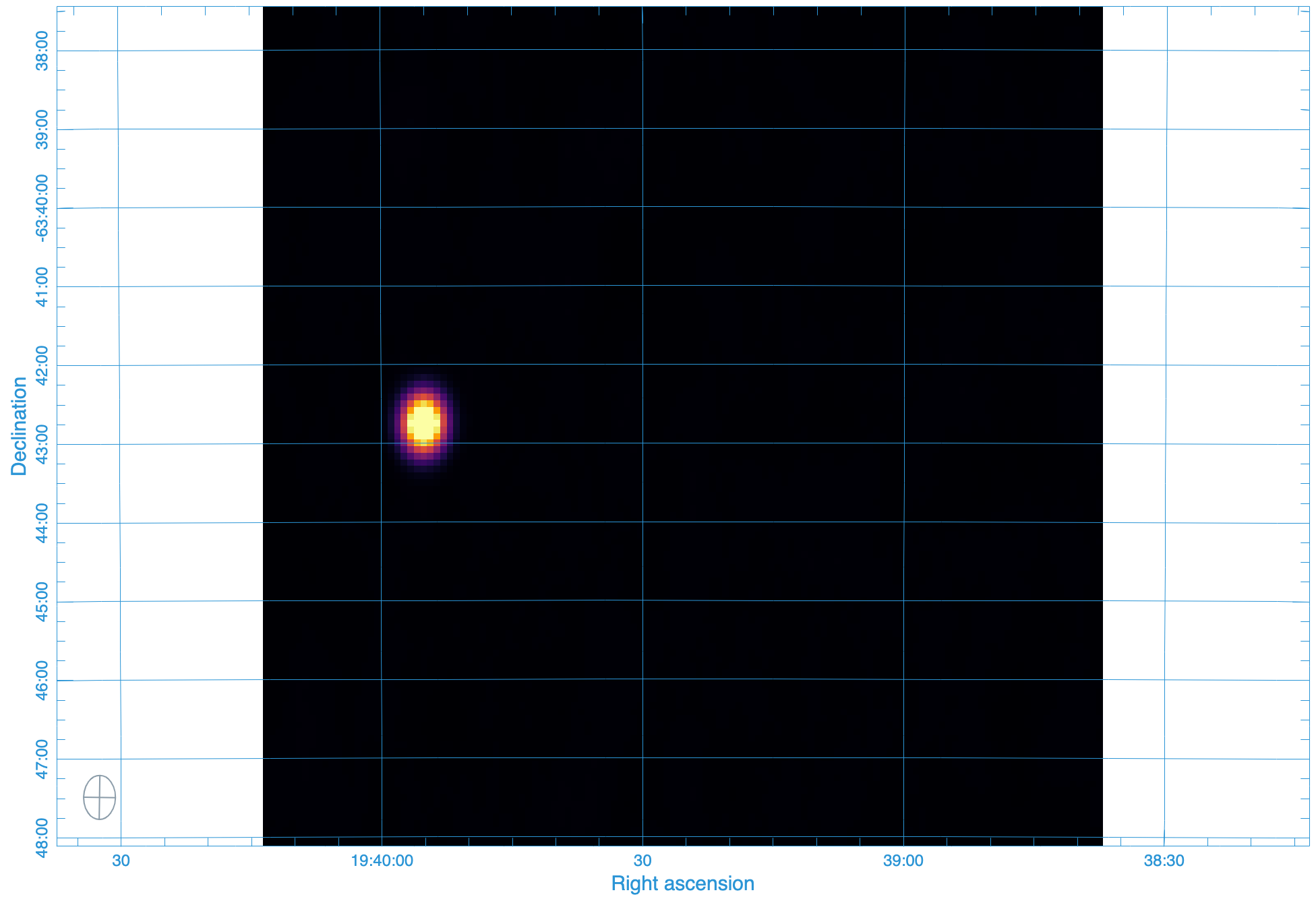
The output image
By the way the output of this pipeline is a not-to-interesting point source:
Running the Test Locally
You can probably see from the CI that running locally should be easy. Afterall you could just follow the same steps. But that would require all the pulling of images and the mounting of directories …. surely NextFlow can make that easier. Yes it can. You can set nextflow to use a docker executor locally.
The nextflow config looks like this - it has multiple sections - this is section I use for my local runs
1 2 3 4 5 6 7 8 | if ( "$HOSTNAME".startsWith("miranda") ) {
process {
container = 'registry.gitlab.com/askapsdp/all_yandasoft'
}
docker {
enabled = true
}
}
|
It’s pretty much that simple. If I am on my local machine, then use the same container as in the CI and switch on the docker executor. I need the conditional as I have other deployment locations.
I have included a config.local in the repo. So the following should work on any machine with docker and nextflow installed
> git clone https://gitlab.com/ska-telescope/sdp/ska-sdp-continuum-imaging-pipelines.git
> cd ska-sdp-continuum-imaging-pipelines/pipelines/yandasoft/nextflow
> nextflow -C local.cfg run functest.nf
Running the RASCIL Checker
There is another nextflow pipeline that runs the funtional test. yanda-rascil.nf the difference being that the
rascil image checker is ran and the test is performed by that image.
process checker {
  container 'artefact.skao.int/rascil-full:0.3.0'
  publishDir 'products', mode: 'copy', overwrite: true
  errorStrategy 'finish'
  input:
     path 'image.cont.taylor.0.restored.fits' from restored_image
     path 'residual.cont.taylor.0.fits' from residual_image
     path 'yanda-rascil-checker.in' from checker_config
  output:
     path 'image*'
     path 'residual*'
     path 'index*'
  script:
     """
     python /rascil/rascil/apps/ci_checker_main.py @yanda-rascil-checker.in
     """
 }
The important difference is that we are now specifying a different image for this process. This pipeline requires docker-in-docker to run. And the test in the CI file is set up slightly differently If a test stage wishes to invoke docker - then the image for the stage needs to deploy with a running docker daemon.
test-yandasoft-w-rascil-w-docker:
when: manual
image: docker:19.03.12
services:
  - docker:19.03.12-dind
stage: test
script:
  - echo "The YANDASoft test- with a RASCIL checker - in docker"
  - apk update
  - apk add ca-certificates curl bash openjdk8
  - cd pipelines/yandasoft/nextflow
  - curl -s https://get.nextflow.io | bash
  - ./nextflow run ./yanda-rascil.nf
  - mv products/* ${CI_PROJECT_DIR}/products/yandasoft/
artifacts:
  paths:
    - ${CI_PROJECT_DIR}/products/yandasoft
You can see it is almost the same - the docker image uses a different package manager. One issue is that the image cache is temporary -so the full image must be pulled each time the test is run. This means the test can take a long time to run. Hence this is a manual test.
The TST-001 simulation
We have also added a cut-down version of the TST-001 simulation as detailed in the continuum imaging pipeline confluence pages https://confluence.skatelescope.org/x/voKZBw
We have made this an optional test that can be deployed from the gitlab pipeline page (e.g) https://gitlab.com/ska-telescope/sdp/ska-sdp-continuum-imaging-pipelines/-/pipelines
The Input Data
The input data here is the gaussian_beams simple simulation and is large (10GB) and it pulled from the google storage using the following steps in the gitlab_ci.
1 2 3 | - echo "deb [signed-by=/usr/share/keyrings/cloud.google.gpg] http://packages.cloud.google.com/apt cloud-sdk main" | tee -a /etc/apt/sources.list.d/google-cloud-sdk.list && curl https://packages.cloud.google.com/apt/doc/apt-key.gpg | apt-key --keyring /usr/share/keyrings/cloud.google.gpg add - && apt-get update -y && apt-get install google-cloud-sdk -y
- cd ${CI_PROJECT_DIR}/pipelines/yandasoft/data
- gsutil -m cp -r "gs://ska1-simulation-data/ska1-low/continuum_sims_SP-1331/gaussian_beams.ms" .
|
The NextFlow Pipeline for TST-001
This is identical to the functional test example all we are changing is the input filenames and the Configuration
The Imaging Configuration
The major difference between this imaging task and the functional test is the size of the input dataset. There are 100 channels and a large SKA-LOW layout. In order to process this on a system the size of a gitlab_ci made a number of simplifications to the Imaging.
We have restricted the longest baseline to 10km:
Cimager.MaxUV = 10000
We have likewise restricted the largest w-term to 3km:
Cimager.gridder.WProject.wmax = 3000
We have restricted the FOV to 4.5 degrees by reducing the resolution to 10 arc-seconds and the number of pixels to 1536:
Cimager.Images.shape                    = [1536,1536]
Cimager.Images.cellsize               = [10.27arcsec, 10.27arcsec]
These are not ideal imaging parameters and have only been used to allow the imaging to fit on a typical runner.
Running the TST-001 Test Locally
This is exactly the same as the functional test - though it will take much longer
> git clone https://gitlab.com/ska-telescope/sdp/ska-sdp-continuum-imaging-pipelines.git
> cd ska-sdp-continuum-imaging-pipelines/pipelines/yandasoft/nextflow
> nextflow -C local.cfg run tst-001-low.nf
RASCIL
The RASCIL pipelines are presented as shell scripts and input files. Instead of the shell scripts, once can also use Nextflow to run the pipeline (see below).
RASCIL runs within the following docker image:
artefact.skao.int/rascil-full:0.3.0
Newer docker images are being released, and the published version tags can be found at https://artefact.skao.int/#browse/browse:docker-all:v2%2Frascil-full%2Ftags
Note: from version 0.3.0 and newer, RASCIL is installed as a package into the docker images and
the repository is not cloned anymore. Hence, every python script within the image has to be
called with the -m switch in the following format, e.g.:
python -m rascil.apps.rascil_advise <args>
The Functional Test
For comparison purposes, the RASCIL pipelines run the same functional test as the yandasoft ones.
The input data
The measurement set for it is included in pipelines/yandasoft/data/functest.ms. It is a small, 8 channel ASKAP simulation.
Running the test locally
Bash scripts
The provided bash scripts need to be run within the rascil-full docker container,
or RASCIL has to be installed on the local machine.
pipelines/rascil/bash/functest.sh provides an example flow of RASCIL pipelines. It starts with
running rascil_advise to
provide imaging parameters for the input CASA MeasurementSet. Followed by
rascil_imager to create
FITS image files. And finally it runs
imaging_qa,
which produces important statistics and diagnostics plots to verify the “correctness” of the restored
and residual images generated by rascil_imager.
Each commandline app uses configuration files stored in pipelines/rascil/config/. Alternatively, one can run the commands by providing the input parameters together with the CLI command. Examples of such runs are pipelines/rascil/bash/rascil-imager.sh and pipelines/rascil/bash/imaging_qa.sh. A detailed explanation of the CLI arguments for each RASCIL application can be found at the links above.
Each bash script assumes that RASCIL is installed as a package into your environment.
Nextflow pipeline
The full imaging and qa pipeline can be deployed via Nextflow. If you have RASCIL installed locally, you should be able to just run the workflow from pipelines/rascil/nextflow (assuming Nextflow is also installed in this directory):
nextflow run rascil_imager.nf
The RASCIL Nextflow pipeline does not use a custom Nextflow configuration file by default, there is no need to set up a local.cfg file and pass that into the command like the Yandasoft pipeline does. If you need to change to configuration, you can update the provided nextflow.config file, which is automatically used by Nextflow.
The outputs of the imaging_qa tool will be saved in pipelines/rascil/nextflow/products. A more detailed explanation
of the Nextflow processes can be found below.
Running the test in GitLab CI
The test-rascil job in .gitlab-ci.yml runs the Nextflow version of the RASCIL pipelines using
the test MeasurementSet.
It pulls the most recent version of the rascil-full docker image (0.3.0 at time of writing).
It installs JAVA, a prerequisite of Nextflow, and installs Nextflow within the pipelines/racil/nextflow directory.
After running the pipelines, it copies the outputs of the imaging_qa tool into the artifact directory.
The Nextflow pipeline
Nextflow-related files can be found in pipelines/rascil/nextflow. nextflow.config contains the basic configuration of executors. Currently, it only contains one option, to run Nextflow with singularity, however, this is a conditional setting, and by default, it will run locally in the local environment. When run in GitLab CI, it uses the docker image provided by the CI job as its local environment.
The more important file is rascil_imager.nf, which contains the Nextflow process definitions. It runs three processes:
- imager
- qa
- test
The imager process
The inputs for this process are provided through the datafile and imager_config channels.
The first one contains the input MeasurementSet, while the second contains the configuration file
for rascil_imager. The configuration file can be found at pipelines/rascil/config/rascil-imager.in.
The output files of the imager, used by the second process, are the restored and residual images, both passed into another two channel, in order to communicate them to the second process.
The qa process
The qa process takes as an input the restored and residual FITS images produced by
the first (imager) process, as well as an input configuration file for the imaging_qa code.
The configuration file can be found at pipelines/rascil/config/imaging_qa.in.
It outputs various figures, CSV files, HDF files, and log files, all of which are transferred into the products directory, generated on the fly in the directory where Nextflow was executed from. These final products can then be inspected to draw conclusions on the correctness of the imaging pipeline.
The test process
This process uses the restored image from the qa process and performs a simple check.
rascil_image_check is
called with --stat max --min 0.495 --max 0.505 parameters. With this set up, we test and verify that
the brightest source in the restored image is 1 Jy. The definition of the stokes I value in
RASCIL is I=0.5*(XX+YY), hence the min-max range is not around 1, but around 0.5.
This process matches the test stage of the YANDASoft Nextflow pipeline.
(See yandasoft for the Nextflow pipeline set up for YANDASoft, which explains their processes in more detail, some of which also applies to the RASCIL Nextflow pipeline.)