Overview
The Mid CBF Engineering Console is intended for integration and testing of the Mid CBF MCS and the Talon DX hardware.
- As required, the Engineering Console will:
Provide emulation of LMC control of MCS
Provide intrusive tools to monitor and control Mid CBF
Access to configuration-managed FPGA bitstreams and Talon DX binaries for deployment to Mid CBF
See MCS-Talon Integration for further details of the integration and test work as it evolves.
Note: MCS does not currently allow its LMC interface to be externally exercised – i.e., it needs to exercised from within the Kubernetes cluster. MCS commands can be issues via an iTango3 shell running in the MCS cluster – see Engineering Console README for details.
System Context
The following diagram shows the Mid.CBF Engineering Console as it fits into the rest of the CSP Mid system.
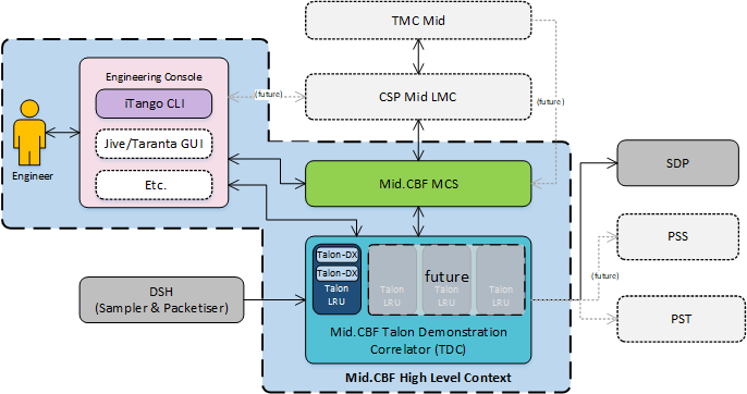
Engineering Console System Context
Interfaces
# TODO
On Command Sequence
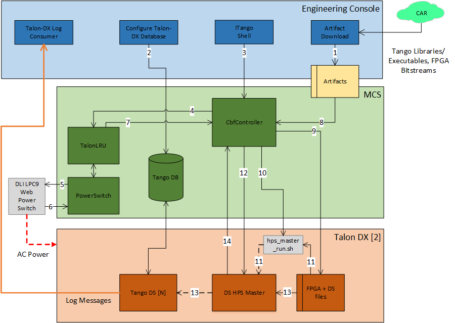
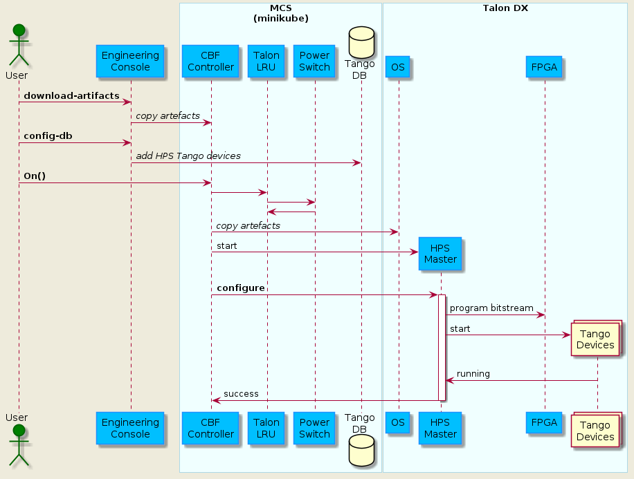
The On command sequence shown in the diagram below is used to automatically power on the Talon-DX boards, copy the appropriate FPGA bitsteam and HPS device server binaries to the Talon-DX boards and start the device servers on the HPS of each board. The sequence is as follows:
Download artefacts (bitstreams and binaries) from the Central Artefact Repository , and build the MCS Docker container after downloading. Optional: Override the DS artefacts with local builds.
Configure the MCS Tango database to add entries for the HPS device servers and the log consumer.
Use the LMC script to send the On command to the
CbfController.The
CbfControllerpropagates the On command to theTalonLRUTango device, which then propagates it to thePowerSwitchdevice.The
PowerSwitchdevice communicates with the power switch hardware over HTTP, requesting power on of specific outlets.The power switch hardware switches the requested outlets on and responds to the
PowerSwitchdevice.The result of the
TalonLRUOn command is propagated back to theCbfController.CbfControllerreads the JSON configuration file in the artefacts folder to detemine which Talon-DX boards it needs to configure.FPGA bitstreams and device server binaries are copied to each Talon-DX board.
The
CbfControllerruns thehps_master_run.shscript on each Talon-DX board to start the HPS Master.The HPS Master device server is started on each Talon-DX board using the copied binary.
The
configurecommand is send to each HPS Master device server.The HPS Master device server programs the FPGA with the bitstream and starts the remaining HPS devices on each board.
HPS Master responds with success/fail result of the
configurecommand.
For a description of how to run this sequence of steps see the Configure the Talon-DX Boards from MCS section.
MCS On Command Sequence
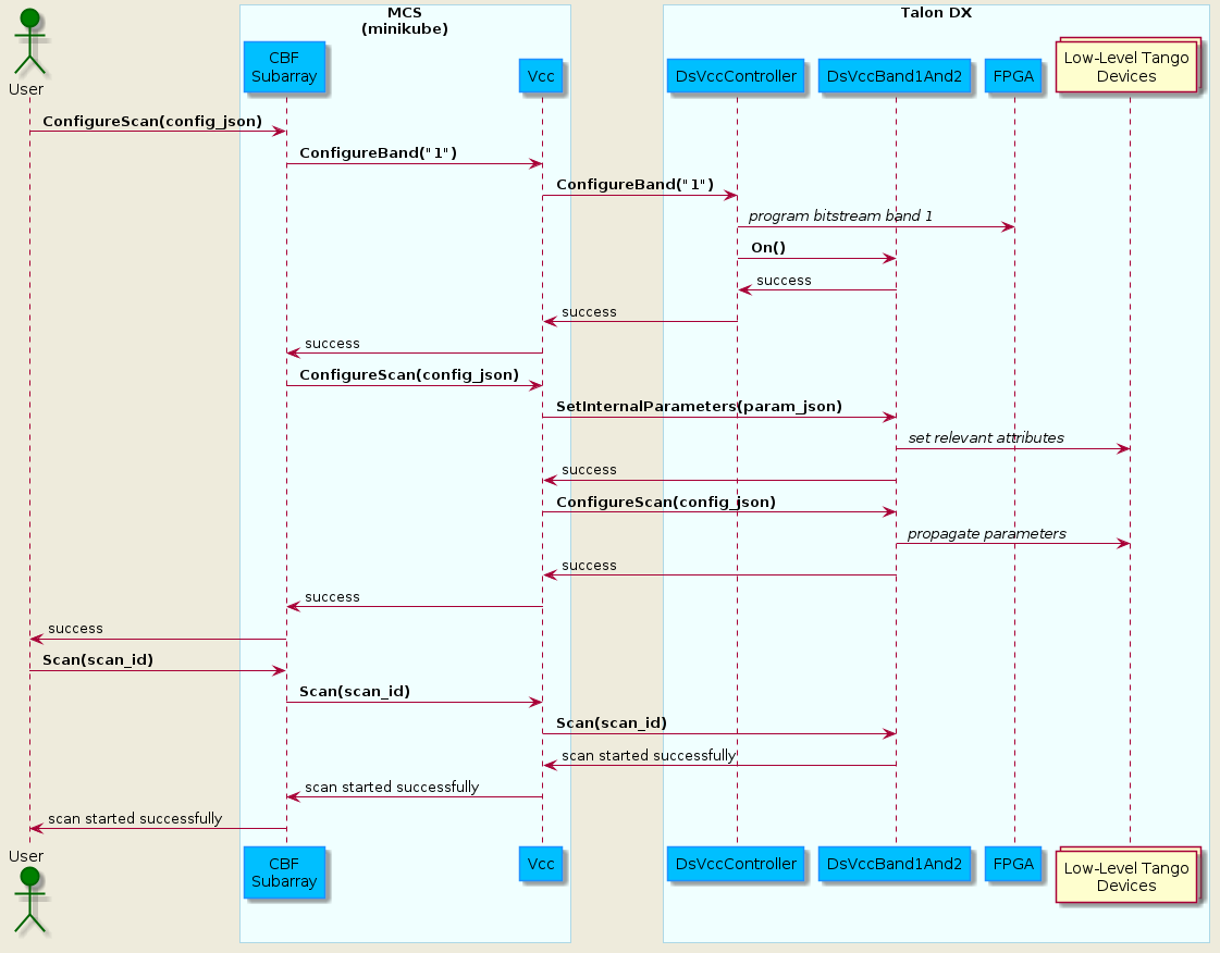
VCC Scan Sequence
Once the system has been turned on using the above sequence, it can be configured for a scan operation. The following diagram shows the flow of scan configuration and execution for a single VCC unit.
For a description of how to run this sequence of steps see the Configure and Execute a VCC Scan section.