Low CBF Firmware - PST
This repository contains the VHDL source code to implement the Pulsar Timing (PST) output product of Low CBF.
This document focusses on PST-specific information, see also Low CBF Firmware Common.
Processing Modules
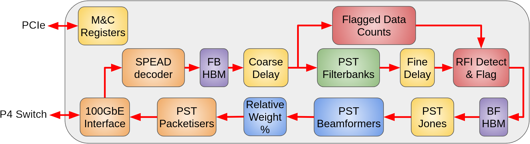
The processing steps are :
Ingest from the LFAA. The LFAA ingest also includes statistics logging and the ability to generate a test data stream.
Filterbank Corner Turn and coarse delay. To limit the overhead associated with initialising the filterbanks, a corner turn operation is required. The corner turn uses the HBM memory. The output of the corner turn is blocks samples about 60 ms long to be processed by the filterbanks.
PST filterbank. 256 point FFT, keeping the central 216 channels, oversampled by 4/3.
Fine delay. Applies a phase slope to the data.
RFI Flagging. Converts from the 16 bit real + imaginary data at the output of the filterbank to 8 bit real + imaginary.
Beamformer corner turn. This takes 60ms blocks of data from the filterbanks and outputs data with all stations for a small number of channels.
PST Beamformer (16 beams) . The beamformer combines data from all the stations to form beams. This also includes Jones corrections.
Per station and per Beam Jones correction. (16 beams) * (512 stations) * (4 matrix elements) * (2 bytes/value) * (2 complex) * (2 coarse channels) = 262144 bytes = 64 BRAMs
Beamformer. Weights are derived from delay polynomials, with a linear approximation for the phase.
Per beam Jones correction
PST packetiser. Packages data according to the ICD.
Building Firmware
The build process is automated via the GitLab CI/CD pipeline, and local builds can be made via the build.sh script in the common module.
Configuring Firmware
The configuration of firmware is through running firmware matlab model which is now a submodule of firmware repo. The model can generate register configurations, stimuli for simulation and verify the simulation result. Details about how to configure is described in details of the configuration process section here
Simulating Firmware
Within firmware repo, there is a sim directory which contains the pregenerated stimuli, register config and vivado simulation script for gitlab CI test. Two stimulis LFAA100GE_tb_data.txt LFAA100GE_tb_data_lesspkt.txt are available to support long and short simulations respectively. These two stimuli files and register config file will be copied to vivado simulation directory when the simulation started. Once simulation is finished, an output file lbus_out.txt will be generated and copied to matlab model run1/2/3/… directory for comparison. The above simulation process is scripted under common submodule: ./common/scripts/xsim.sh for simulation automation.
Verifying Firmware
Within matlab model repo, matlab function rtl_model_compare is used to compare the rtl output and model output, rtl_model_compare(1) will trigger a long simulation verify, rtl_model_compare(0) will trigger a short simulation verify. Compare will generate standard deviation between model and RTL, as the model is float point, RTL is fixed point, as long as the stand deviation is within the specified range, then compare is regarded as passed. Matlab script under common submodule: ./common/scripts/matlab.sh is used for the compare automation.
The matlab compare function is calling the matlab model function run_PSTmodel which user can refer the details of the verify process section here