Names used within Low.CBF
P4 network switches (P4s) and Alveo cards are key hardware elements of Low.CBF, together with IO connections to LFAA, PST, PSS, and SDP. Software identifies the items it manages by means of a unique name. Names include:
Switches: “p4_01”, “p4_02” (or we might use a serial number)
Switch ports: “10/0”, “3/1”, ie port number/lane
Alveo cards: “alveo_000”, “alveo_001” (or a serial number)
PST servers: “pst_01” (or IP address). Each server will be associated with one switch port.
PSS servers: “pss_01” (or IP address). Each PSS server will be associated with one switch port.
SDP servers: “vis_01” (or IP address). Each SDP server will be associated with one switch port.
Stations: “stn_001” (or IP address). Each station will be associated with one switch port. All of a station’s substations, if any, will connect at the same switch port.
Description of Low.CBF Structure
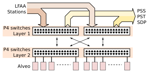
Low.CBF has two network switch layers. Stations and IO connect to the first layer of switches. Alveo cards connect to the second layer of switches. Each first layer switch is connected by optical links to every second layer switch, allowing data from any station to reach any Alveo for processing, and data products from Any alveo to be sent to any IO link. (Note: the first two array releases are exceptions with only a single switch.)
Software learns the structure of the connections between Alveo cards, P4 switches and IO links by means of a list of interconnections provided to it. (The list could be derived from a resources table or by a self-discovery mechanism.) There are three general classes of connections:
- switch-to-switch, eg:
{“switch_id”: “p4_01”, “switch_port”: “10/0”, “ switch2_id”: “p4_08”, “switch2_port”: “2/0”, “speed”: 100}
- switch-to-Alveo, eg:
{“switch_id”: “p4_08”, “switch_port”: “11/0”, “alveo_id”: “alveo_000”, “speed”: 100}
- switch-to-I/O link, eg:
{“switch_id”: “p4_00”, “switch_port”: “2/0”, “io”: “stn_001”, “speed”: 100}
{“switch_id”: “p4_00”, “switch_port”: “3/1”, “io”: “pst_01”, “speed”: 25}
{“switch_id”: “p4_00”, “switch_port”: “4/0”, “io”: “pss_01”, “speed”: 100}
{“switch_id”: “p4_00”, “switch_port”: “4/0”, “io”: “sdp_01”, “speed”: 100}
The concept of Frequency Slice Processor (FSP) is used to represent Alveo processing hardware. FSPs are groupings of Alveo cards, programmed with the same firmware, and attached to the same P4 switch. Each FSP usually consists of 8 Alveo cards, but will consist of just one Alveo card for the first array release. FSPs have a defined bandwidth they can process. The bandwidth varies for each type of FSP (Timing Beam, Search Beam, Standard Visibility, Zoom Visibility).
There will be a catalog of firmware images that is available to run on FSPs
Once software has analysed the connections list to determine which Alveo cards are attached to each switch, it groups the Alveos into FSPs. If the number of Alveos attached to a switch is not a multiple of the grouping, the remainder cards will not be used.
Subarray Resources
During Subarray resourcing, FSPs and P4 switches are assigned for use by Subarrays. By default all resources assigned are shared so that every Subarray is able to use every switch and FSP, but resources can also be exclusively assigned to a Subarray. Exclusive ownership is a mechanism to create hardware groupings that can be operated independently of other hardware, for example testing or maintenance purposes.
As part of resourcing, FSPs are assigned a “personality” (the FPGA executable) which determines whether it calculates visibilities, search beams or timing beams. All Alveos in the FSP are programmed with the same FPGA binary executable.
FPGA executables are selected from a catalog that contains the name of the personality and a description of its capabilities (stations, bandwidth). Some beamformer images can be further parameterised during resourcing (e.g. can calculate a greater bandwidth if the number of stations is restricted).
The resources used by each Subarray can be summarised as two tables – one table for FSPs and another for P4 switches. Tables contain a row for each FSP or P4 switch. Columns indicate the status or configuration of the resource and also show which of the Subarrays have it assigned for their usage.
P4_id |
Health |
AdminMode |
OpState |
Firmware |
Mode |
Shared |
Subarray_01 |
Subarray_16 |
Accessible IO |
|
|---|---|---|---|---|---|---|---|---|---|---|
P4_01 |
True |
Assigned |
Assigned |
sdp_01, pst_3 |
||||||
P4_02 |
False |
Assigned |
pss_05, pst_4 |
Assignment of a P4 switch to a Subarray allows the Subarray to access the IO and FSPs connected to the switch. The final column in the P4 table indicates the IO resources the switch can make accessible to the subarray: stations, PSS/PST/SDP servers, and FSPs.
FSP_id |
Health |
AdminMode |
OpState |
Firmware |
Mode |
Shared |
Subarray_01 |
Subarray_16 |
|
|---|---|---|---|---|---|---|---|---|---|
FSP_01 |
PST:0.0.1 |
pst |
True |
Assigned |
Assigned |
||||
FSP_02 |
PSS:0.2.1 |
pss |
False |
Assigned |
How Subarrays acquire hardware resources
Subarrays make requests to the Low.CBF Allocator device when they want to acquire or release hardware resources resources. Hardware resources are either:
P4 network switches (P4s) P4s route data from LFAA to the Alveos and then route data products from the Alveos to PSS, PST and SDP servers.
Frequency Slice Processors (FSPs) FSPs are sets of Alveo FPGA cards that perform signal processing. All Alveos in a FSP will be programmed with the same firmware image.
When acquiring or releasing these resources a subarray identifies the resource by its name, and specifies the access mode it wants for the resource (shared or exclusive). The first subarray to acquire a resource must also specify firmware image and version together with a mode in which the firmware is to be configured. The specification is provided to the resource allocation or de-allocation command using a JSON string as the command argument, eg:
The result of the command will be two concatenated tables, one indicating the current status of each P4 device, and the other indicating the status of each FSP device. The tables are provided as a JSON string returned from the command e.g:
If a subarray needs to determine resources that are available, it can issue a resource allocation command with an empty resource request.
Subarray Capabilities
It will be possible to query the capabilities available to any Subarray at any time, before, during or after resource assignment. The capabilities include a number of beams, visibilities, channels, station inputs and IO outputs that are possible from the shared and exclusive resources available to a Subarray. After resource assignment is complete, Subarrays may use this information to determine the limits of the capabilities that they can configure for a scan. Since resources may be shared, subarrays contend for the shared resources, and will be served on a first-come basis.
Before a Subarray runs a Scan, it will attempt to allocate some or all of the capabilities available to it for exclusive use during the scan. This capability allocation may fail if other Subarrays have claimed part or all of the capabilities or resources needed. It could also fail because of resource fragmentation (can’t pack all the configuration requests into available resources without having to reshuffle allocations) or because IO needed by the Subarray (particular stations, servers) is not available at the P4 switches assigned to the Subarray.
Once a Subarray is resourced and configured however, a subarray will retain its resources and capabilities until it releases them.
How Subarrays configure capabilitys for Scan
Once a Subarray has resources, it has the capabilities needed to scan. Before it scans, it needs to configure the capabilities it intends to use. Subarrays perform configuration by making requests to the Low.CBF Allocator
(yet to be completed)